Hi,
where do you get the DC power from for the Buck converter?
I assume, the entire system only has a single 24AC power supply that powers both the valves and the controller. In this case do you have an AC-to-DC converter before the Buck converter?
Or do you have a separate power DC power supply?
Cheers Ingo
1 Like
Hi Ingo,
The IC in the power supply for the controller accepts any input voltage from 5V to 37V, AC or DC. 24VAC connects to this power supply and produces 5V output.
GitHub Link.
So 24VAC 1A plug pack powers both controller and solenoids.
Parts sourced from Jaycar.
Regards
Jim
1 Like
Hi @James46717, Thanks for sharing this project - it’s really useful.
A quick follow up to Ingo’s question though. Maybe my electronics is a bit rusty, but I am struggling to understand how an AC signal can be applied to the input, particularly given there is a polarised capacitor there. It hasn’t blown it? My understanding is that that this circuit (and the LM2678) is only designed for a DC input.
Am I missing something?
Cheers, Ed
1 Like
Hi Ed
Welcome
No, I don’t believe you are missing anything.
You are correct in that the data sheet for the LM2678 does not mention any AC input capability and the suggested circuit for that buck converter certainly suggests a DC input and with all those polarised caps to ground I don’t think it would like AC at all.
Unusual for James but unless he has dived down a bit deeper that the data sheet for that chip he has made an unusual mistake or omitted some sort of rectification for the AC.
The 24VAC has been discussed at length previously but is the operating voltage for the commonly available (I believe) water solenoids he uses (with success). He could rectify that and use the resulting DC as an input for such a device without interfering with the AC solenoids.
Cheers Bob
I just had a look back through this thread and James’ project. and yes, he has used that linked buck converter circuit and has applied 24VAC to the converter input directly. Apparently with success. Jaycar also promote AC input.
So, if you are missing something I am missing the same thing. Perhaps James if you have found out more about this chip that is in the data sheet could you please enlighten us.
James has only used 1 22µF capacitor on the input. The reactance of 22µF at 50HZ is 144Ω which you may get away with. The published circuit uses 3 in parallel which is 48Ω which I think would shunt away 0.5A unless it blew something up while doing this.
1 Like
Hi All,
The smart controller was an exercise in “can it be done”, it has been in my parts box for a few years now, currently using a much simpler relay design.
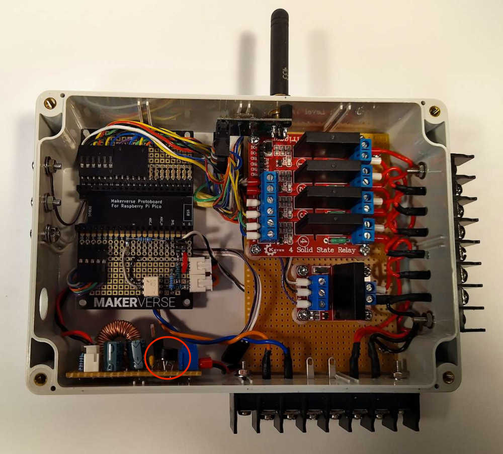
I pulled the smart controller apart and surprise surprise it uses a 4 terminal bridge rectifier. You can see it in the pics next to the blue input terminals.
I will update the schematic and post it here, maybe Core can get the project schematic changed.
Sorry it was not in the original, don’t know why I didn’t put it there. With all the aspects of this project, it was overlooked. Good example of why you should have more than one set of eyes checking stuff.
Cheers
Jim
Updated Schematic. And fixed capacitor values to what are actually on the board.
Schematic 01a.pdf (212.7 KB)
PS Sometimes my documentation is severely lacking, and when I come back to an old project it frustrates me trying to understand why I did what I did. Now trying to have better documentation on current projects.
1 Like
Hi James
That makes a LOT more sense. I did not spot this previously mainly because I did not look. I knew it was a watering system and I knew you used 24VAC water solenoids and why. But that is as fat as I got as a watering system did not particularly interest me. I only chipped in regarding the use of solid state relays.
Anyway, all fixed and everybody should be happy.
Cheers Bob
Just had a look at your original project docs.
Interestingly that bridge is not apparent in the Pic “Power supply Parts” but is very visible in this one.
I note that you used bootlace ferrules in your terminal block connections. If everyone did this I think there would be a lot less potential problems.
1 Like
Thanks for coming back on this and updating the schematic, @James46717 - much appreciated. I am just building a similar device at the moment and good to know that I’ve not overlooked something. Cheers, Ed
P.S. For what it is worth, your “severely lacking” documentation is still better than my best examples!
1 Like