Robert just shared a new project: "Potentiometer Position Monitor"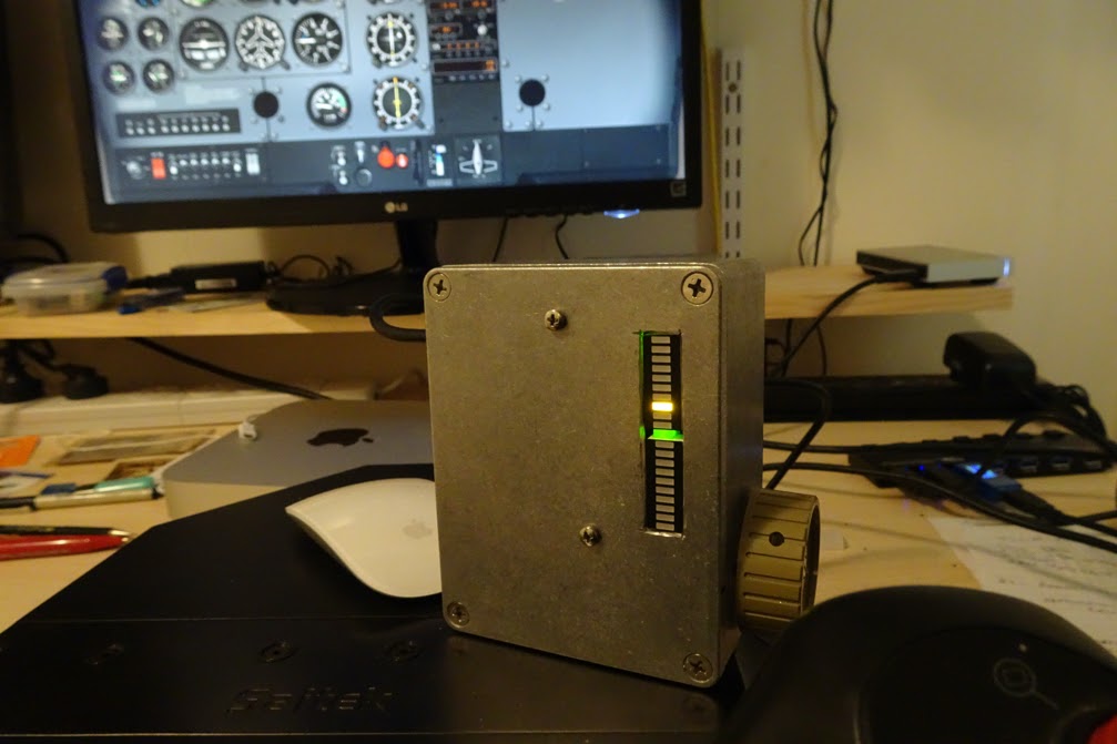
This project started out being a method of displaying the approximate position of a 10 turn pot. Quickly expanded into a full-scale Flight Sim add-on. I initially intended to use the 10 turn pot in the Flight Sim but the project is the method I used to display approximate position at a glance. I initially used a turns counter but despite being far more accurate was a bit inconvenient as I had to search for and interpret the small numbers.
Read more
9 Likes
Great to see this finally up! Thanks for sending it in Bob 
6 Likes
Nice idea, will remember when I get into something complicated like the multi-turn pots. Thanks Robert.
6 Likes
Hi G
Glad to help in any way I can. But there is nothing strange or complicated about a 10 turn pot. Coupled with a reasonable quality turns counter repeatability can be pretty good.
I have such a combination along with a rotary encoder (all Bourns) set up on a bracket on a base board along with an Arduino and proto board for experimental purposes.
Cheers Bob
Edit. I used the 10 turn pot here for smoother control and more realism for elevator trim in the flight sim.
5 Likes
Hey Bob,
Glad we got this one released! We’re clearing through the backlog we’ve got here at the moment.
Creative use of the bar graph LEDs, if you’ve got any photos of the complete flight-sim rig that you’re putting together when you’ve got it all assembled we’re all keen to take a look 
All the best with your projects Bob! And as always, thanks for posting on the forum yet again!
2 Likes
cool for those who have need
2 Likes
Hi Bryce and All interested
Please accept apologies for being so very slow to respond. I have been very limited in work space for the last few years so cannot progress as quickly and smoothly as I would like. Almost down to the kitchen table situation.
This project has snowballed and is not yet complete. Very much a work in progress. Getting there.
Recap: I had a 10 turn pot assigned to an axis for elevator trim on my flight simulator. My main problem was finding centre position being unable to directly see the turns counter I had fitted. Years ago (Picaxe days) I had a system to control speed and direction of a small motor with a single pot, centre being off. I modified the concept to use Arduino and LED bargraphs to achieve the result documented above.
This worked well but having 2 boxes was pretty cumbersome so tried something new. Graduated (or promoted sideways) to a rotary encoder for this purpose with the push button zeroing to “Take Off” position. As I am already using a Leo Bodnar joystick board and 9 other rotary encoders this was pretty easy and everything fitted into the grey box. But, I thought the LED indicator would still be nice.
The next problem, sharing the rotary encoder with the Leo Bodnar board and Arduino. Unfortunately the method of processing button pushes on L B board and Arduino are vastly different. LB system strobes a matrix to detect button presses while Arduino switches to Gnd or logic high. L B support could not offer any solution as if I wanted to ground 1 row this would upset the strobing operation for that row.
They do however have another solution. L B make a version of this controller in which all 36 buttons are taken to ground when operated. Still does the same, 4 inputs for top hat plus 32 buttons or 16 rotary encoders or any combinations. This would seemingly solve my sharing a rotary encoder problem. I have ordered and currently await delivery of this board.
I have also transferred the Pitch and Roll axes to the L B board to get rid of the Saitek built in “dead zone”.
I attach a couple of pics of the current state of play. The 10th rotary encoder can be seen tucked in at the end of the L B board.


The function of the 9 encoders are:
Top row. Nav 1 Tune. Radial select, Tune coarse, Tune fine.
2nd row. Nav 2 Tune. Radial select, Tune coarse, Tune fine.
Bottom row. NDB Tune. kHz X 100, kHz X 10, kHz X 1.
The new L B board is larger so I will not have enough real estate. Need a bigger box.
Will keep posted but may be a while getting delivery of new board, still getting Xmas cards from UK.
Cheers Bob
5 Likes
Hi All
Just a quick update.
Postal tracking tells me mu new board arrived in Sydney last night (13/01/22) and is currently waiting to be cleared. Should not be too long now.
Have a few experiments to do before final circuit decisions but it is then full on.
Watch this space (as the saying goes).
Cheers Bob
4 Likes
Hi all.
A quick update.
My Leo Bodnar board arrive a couple of weeks ago (time flies) but I have been a bit busy.
I have gone for a bit of a modular approach so I can check different aspects as stand alone bits.
The Rotary encoder processing and elevator position module is complete and checks out OK. I used an Arduino Pro Mini as the micro controller and the bargraph and most of the circuit from the previous unit. The whole thing is built as a stand alone unit on a MakerVerse proto board. The only thing I have to provide on a temporary basis is a couple of 10k pull ups for the encoder. This is provided by the LB board in the finished setup. This module will be powered from the LB board or for stand alone testing by the USB input.
This indicator unit has just now been temporarily combined with my new Leo Bodnar board and XPlane 10 flight sim complete with pitch and roll axes. This check was to make sure the Arduino and the LB board can share the same rotary encoder happily. I can report success here as each unit seems content with he presence of the other and all systems fine.
There is one more button shared, the push switch on the encoder and a button on the LB board. This returns the flight sim to the default “Take off” position and returns the indicator to centre position. The indicator returns to default centre simply by re setting the Arduino with the “reset” pin.
The next step is to put the whole thing together in a new larger box with the other 9 encoders. The jury is still out on whether I include the flaps lever switch at this stage and I might leave that for another day. The LB board has plenty more expansion capability yet.
Watch this space.
Cheers Bob
5 Likes
Hi All
At Last. My apologies for the long delay.
Well I have got this final version up and running at last. Actually it has been finished for a couple of weeks now but to produce a schematic I have been getting my head around KiCad. It is the first time I have used it. I had a bit of fun navigating the component libraries. For instance a common resistor, one would be entitled to think you would find it under “resistor”. Not so, I found it under R-US and R-US Small. Never mind. I eventually found what I needed. I had to improvise with the Arduino Pro Mini but that was not a great problem.
The Leo Bodnar interface BU0836 is now BU0836X. The BU0836 has the buttons in a matrix configuration and the scanning system used for button presses does not allow the parallel use of the Arduino system. The BU0836X unit brings each button out to separate connectors and they are referenced to ground. This allows happy sharing of the encoder buttons between Arduino and BU0836X unit. The down side to this unit is firstly physical size compared to the previous and the very small “push in” connectors. Recommended wire size is 24AWG to 20AWG but I think you would be struggling with 20AWG, particularly stranded wire. I used 24AWG but found to get it successfully into the connector I had to tin it. I stripped about 6mm and used a heavy iron tip to carefully and quickly tin right on the end using only a tiny amount of solder. This wicked up the wire only about 5mm and I thought I should get away with this being a spring loaded connector minimising the solder creep situation which sees tinned wires under screws come loose after a time. I still found it best to depress the button to open the connector while inserting wires.

Sorry I don’t seem able to insert the KiCad schematic directly but here is a .jpg version.
The Schematic is pretty self explanatory. The Arduino has changed and a rotary encoder replaces the 10k pot. The LED arrangement is pretty much the same. The flap control has been removed (for now) but I may put it back later. R5 / C1 and R6 / C2 are debounce filters and are required for the Arduino. Pull ups are provided within BU0836X. I saw somewhere that button de bounce is taken care of within BU0836X and I have had no problem with this with any of the encoder connections.
The Arduino is powered from a BU0836X 5V output which is in the Blue group of connectors. The button on this “elevator Trim” encoder is “reset to Take OFF position and uses BU0836X button 11 and simply resets the Arduino back to start.
The rotary encoders are Bourns PEC11R-4120F-S0018.
The sketch (I hope)
// Rotary Encoder Inputs

 Encoder myEnc(2, 3);


const int ledCount = 11;    // the number of LEDs in the bar graph
const int ledUp = A1;        //LED bank nose up
const int ledDn = A2;       //LED bank nose down

int ledPins[] = {
 9, 8, 7, 6, 5, 4, 10, 11, 12, 13, A0
};   // an array of pin numbers to which LEDs are attached

void setup()
{

  //LED Bank switching, LOW active
 pinMode(ledUp, OUTPUT);
 pinMode(ledDn, OUTPUT);

  // loop over the pin array and set them all to output:
  for (int thisLed = 0; thisLed < ledCount; thisLed++)
    {
      pinMode(ledPins[thisLed], OUTPUT);
    }
  //Setup Serial Monitor
  Serial.begin(9600);//Left in for Debug/Set up use

}
int  oldPosition = -999;

void loop()
{
  //Do some useful stuff here
int  newPosition = myEnc.read();
  if (newPosition != oldPosition)
   {
    oldPosition = newPosition;
  int count = (newPosition/16);// 4 events per detent. /4 = 1 count per detent
                               // /16 = 1 led change per 4 detents
                               // To change alter division in multiples of 4


  int LedLevel=count;
    Serial.println(LedLevel);

    if (LedLevel > 0)
    {
      digitalWrite(ledUp, HIGH);//ledUp nose up bank OFF:
      digitalWrite(ledDn, LOW);//ledDn nose down bank ON:
    }

     // change sign for ledLevel when pot below centre:
     if (LedLevel < 0)
     {
      LedLevel=(LedLevel * -1);
      //switch led banks:
      digitalWrite(ledUp, LOW);//ledUp nose up bank ON:
      digitalWrite(ledDn, HIGH);//ledDn nose down bank OFF:
     }

     //keep LED 10 on when potentiometer outside monitor range:
      if (LedLevel >= 10)
      {
        LedLevel = 10;
      }

       // loop over the LED array:
      for (int thisLed = 0; thisLed < ledCount; thisLed++)
        {
          // turn the pin for this element on:
          if (thisLed == LedLevel)
          {
          digitalWrite(ledPins[thisLed], HIGH);
          }
          // turn off all pins other than the ledLevel:
          else
          {
          digitalWrite(ledPins[thisLed], LOW);
          }


          {
            //Serial.println(count);// For Debug/Set up use
          }
        }
  }
}
Well that seemed to work.
The sketch is also fairly self explanatory. The main difference is using encoder “newPosition” instead of re mapped ADC outputs. There are 4 “events” per encoder detent so every detent results in a count of 4 which means “newPosition” has to be divided by 4 to get a proper detent count. For my application at the moment I am advancing (or retracting) 1 LED per 4 detents which suits my purpose at this time. I do this by dividing by 16. This can be easily changed with this division but must always be a multiple of 4. The “Serial.println” has been left in to enable monitoring / debug operations.
The Pics.


Finally the Pics. Two are views of the internals. I think everything is shown clearly. The BU0836X connectors are colour coded. Orange = 8 x analog 12 bit inputs, Blue = 4 x push buttons reserved for Hat Switch operation plus 1 for 5V output. Grey = 32 x digital or push button connections, this can support up to 16 rotary encoders. The 2 analog connections are the simulator Roll and Pitch pots to bypass Saitek’s built in “dead zone”.
The 3rd Pic is the front view in operation.
Cheers Bob
4 Likes
Hi Bob,
If you like the rectangle looking resistor typing in ‘r’ will yield something quickly:

Very neat wiring!
If you have any questions about the software itself I’m sure everyone would be more than happy to help out!
1 Like
Hi Liam
Being a bit naive I typed in “resistor” and got nothing. Didn’t really take me long to discover “R-US” as being what I wanted.
Could have been a little better but I did not want to completely rewire all 9 encoders so I used existing wiring and connected to buttons within reach. Just made it as you can see. I had already wired this in groups, Wh = A sw, Bk = B sw and a colour for common, Bn = enc 1, Rd = enc 2, Or = enc 3 and so on. As I had to re allocate each button within the Flight Sim it did not matter as long as the convention of using the buttons in pairs with the odd number first (1 & 2, 3 & 4 etc) is followed as outlined in Leo Bodnar’s instructions
I am sure of that. I might just take up on that once I have waded through the Help section.
Cheers Bob
2 Likes