Rapid slew, heavy weight pan tilt hyperspectral platform

Hi, I need to construct a pan tilt platform that will carry approximately 10kg of optical equipment.

All up moving weight may be about 15kg.

Constructing this system mechanically is not a problem, but items like shaft couplers and bearing blocks available with the chosen motors may make life easier.

A 360 degree pan turntable fitted with a fork mount tilt mechanism seems the best design option.

Pan tilt accuracy does not need to be to astronomical precision. +/- 1 degree is OK, ½ degree better but absolute pointing accuracy is not as important as the ability to move rapidly and settle on a new pan tilt pointing position. The platform must settle rapidly (0.5 sec) when it stops at a new pointing location.

The pan platform should be able to slew 180 degrees in 2 to 3 seconds meaning significantly powerful servos and drivers are needed. Duty cycle will be very low at this speed, < 1%, but the rapid pointing movement may well be at the motors thermal and electrical limits for a couple of seconds.

The tilt platform should be able to go from horizontal to 90 degrees (up) in the same time frame. Ideally, the tilt servo/motor will allow for 180 degrees of movement, ie horizon to horizon through the zenith but < 90 degree operation will be usual.

The Pan platform should be able to move through 360 degrees or almost 360 degrees, maybe limited only by the angular space occupied by safety limit switches if they end up occupying a small segment of the 360 degree pan arc.

I am looking at your 5303 geared DC motors with encoders and possibly the electronic driver RoboClaw 2 x 60 A.

Command and control will come from a laptop ideally via USB but other serial (RS232) or parallel connections could be designed in. RF connectivity is not preferred at this time.

Do you have any comments regarding product selection of 5303 geared DC motors with a RoboClaw 2 x 60 A controller or are there better options?

Can these motor/gear boxes be manually pushed if depowered or would I need clutches to detach them if the platform needs to be manually rotated? Ideally, I would like to depower the motors but leave the shaft encoders on line so pan/tilt tracking calibration is retained.

I am assuming that a stepper motor through a torque multiplying gearbox will be too slow. Is this assumption correct?

Thanks for your help.

Cheers

Mike

1 Like

Hi Mike

I think you might be entering fairly robust industrial area here. Have a think about trying to stop 15kg at this speed with 0.5 or 1º accuracy without bending something. You have quite a bit of rotating inertia to overcome. Even motor over run could be a problem as the motor required to move this load in the first place might be quite large.

I am not implying it can’t be done as similar things I am sure exist in the industrial world. What I am suggesting is this could be getting a bit borderline at Hobby level and you may need some professional engineering advice.

Cheers Bob

Add on. You would possibly have to think about acceleration up to speed and deceleration when approaching the required position so that braking to stop at the required position would be mechanically less stressful. This might lengthen your timing but the whole thing might have to be a bit of a trade off. It could be a bit hard (read expensive) to get the best of both worlds.

Thanks Bob.

Most controllers have at least three custom settings in them that allow you to set maximum speed, acceleration rate and deceleration rate for each motor/servo. The pan tilt frame will be very stiff and strong, but the stress on the drive gearboxes could be a bit borderline if the acceleration and deceleration settings are too harsh - just as you say. If necessary, I can assist the deceleration with a clutched brake on a solenoid, but it is the pan speed and acceleration I am not sure about. The chosen motor/gearbox specification seems to indicate that this combo can produce sufficient torque but I don’t know anything about the controller or real world experience with the motor/gearbox units. I’ve searched extensively for commercial units that might be suitable but haven’t found anything that suits yet, hence considering making what is needed. Astronomical drive units are more than capable of carrying the weight but are very slow. Large security camera pan tilt heads are AC driven, still too slow and not capable of looking straight up.

Any experience or pointers are appreciated.

Mike

1 Like

Hi Mike

I do have some experience with what I suppose you could call similar situations.

Some 25 years ago I was helping out streamlining and automating some manufacturing and testing processes at a small factory. One project was the modification of some older coil winding machines to operate under PLC control instead of the old turns counters. The techniques for easy acceleration and deceleration were not around those days so the system was 2 settable speeds so the spindle could be slowed when approaching a stop point. It was this stopping at the correct point that was the problem. The coil mandrel was quite heavy and had a fair bit of inertia when spinning. There was an electromagnetic brake which was activated when the driving motor power removed but even with the assisting wire tension this was no where near enough as the spinning motor added to the forces applied. Adding some electric braking to the system by arranging a low value high wattage resistor across the motor windings when power removed coupled with the slow speed when stopping solved this particular problem and enabled the stopping position to be accurately repeated. The finished system with PLC control etc has been running now very reliably for some 25 years.

Another scenario is limit switch over run. With some arrangements it is possible with motor run on to go past a limit switch and re activate the motor power so everything keeps going. This is usually prevented by using a NO/COM/NC changeover limit switch and arranging a diode to be switched across the motor to apply a short circuit thus stopping it virtually instantly.

A similar situation to yours might be with the auto tuning system in high power HF radio transmitters where the tuning components have to be driven rapidly to the correct point. In my experience this was done with “zero seeking” amplifiers but you don’t want the motors slowing down as the tuning point is approached and the error voltage signal is decreasing. Positive feedback is used to keep the motors driving pretty fast right to the zero error point where they come to a fast stop. Electronic braking is achieved by keepingg the motor connected to the almost 0Ω output source resistance of the amplifier which believe me causes instant stopping.

The above scenarios used brushed DC motors.

At the other extreme considering the driving mechanism. You might be able to use several motors. Think of a very large object like the Parkes Radio Telescope. This rotates on a very large flat ring and sits on this ring via many rollers like a giant roller bearing. Each roller is driven by quite a small motor but in this case many of them. I have been up on the dish and marvelled at the simplicity of the whole thing. Which is pretty amazing when you consider the structure must weigh several hundred tonnes. Something similar on a very much smaller scale might work for you.

Cheers Bob

3 Likes

Very helpful Bob!

Thanks.

I worked at Orroral Valley tracking station near Canberra as a first job out of uni so moving big antennas is not an unfamiliar theme. The Orroral dish had to slew very rapidly to catch LEO spacecraft including the Space Shuttle. I was in the electronics section, not mechanical support though. Orroral used hydraulic motors on the 32M dish and I have considered them for this job. As an aside, the Orroral main dish had to run a rapid spiral search pattern for the Shuttle because we never knew exactly where it would pop over the horizon…we were the first station to acquire the Shuttles in a narrow beam antenna after launch. The hydraulics made quite a racket when running hard.

I’m retired now. This job is a very interesting, (to me anyway), rapid pointing hyperspectral image acquisition system and I need to keep the costs reasonable.

I should have considered switching a load or a short across the motor. Great idea. A short might cause serious gearbox stress but a calibrated load sounds good. Also, the option to use multiple motors. That probably puts me back into a belt, gear or chain drive on the pan platform so two motors can share the load. Backlash control then becomes an issue but that should be manageable. As mentioned, the system does not have to be super accurate as the sensor coverage is about 8 degrees.

Do you have any comments on using a large closed loop stepper motor compared to a DC motor with shaft encoder? Both must be geared.

Cheers

Mike

3 Likes

Hi Mike

Interesting. I spent a fair bit of time at Honeysuckle Creek, Williamsdale and Red Hill. Installed and stayed on site to maintain 7GHz temporary link system for the Apollo Missions in the late 60s and very early 70s. From what I remember the dish there was on 2 geared quadrants to move 180º in 2 directions 90º apart. The down side to this is the antenna polarisation had to be continually compensated as the dish “rotated”. All good stuff. I think there was a 20kW Klystron hanging underneath for transmission.

Worked OK. Of course a diode is a short and I simply made the resistor I fitted on the winders about the same resistance as the motor winding, figured you can’t get into too much bother with excessive current that way. About 4Ω from memory.

I personally would think a bit about having the encoders on the motor(s). I would be more inclined to fit an encoder ring on the platform with sensors on the base. Or fit an absolute encoder to the rotating platform. Or even a precision potentiometer for positional feedback. Like a Servo motor.

That zero seeking amplifier I mentioned would have merit here. I have the circuit somewhere as I was going to use it for sun tracking. I will see if I can find it, no luck so far. To morrow’s task.

I don’t have any practical experience with steppers I am afraid. I know they are everywhere but I have not had a need to pull anything apart.

Cheers Bob

3 Likes

Hi Mike

Well, I have searched high and low and unfortunately have not been able to find any trace of that servo amp circuit for transmitter tuning I mentioned. Memory details are pretty hazy after 30 years and would you believe even after many years with a fair bit of association with these units I have never had to touch this unit. Built to last they were.

I can however give you some idea on how this worked which may be of some help to you. I will only attempt to describe the “coarse” positioning as this would be the only bit you would be interested in.

On receipt of a “tune” request a CW RF signal is sent to the preamp, the output of which is inhibited at this stage to prevent disasters. This preamp contains a discriminator which provides a DC output (+ or -). This DC then becomes the “go to here” reference. Positional feedback is provided by a precision multi turn (10 or 20, I forget which) potentiometer. Comparing the 2 voltages provides an error signal which is used by the servo amps (4) to drive the corresponding tuning elements to the correct approximate positions. This was all analog so as the position gets closer of course the error signal will get smaller and the motors will get progressively slower and possible never “get there”. This was overcome by an ingenious positive feedback system so the motors drove full on until the zero point reached then came to an abrupt stop. I can’t remember exactly how all this feedback works which is why I wanted to find the schematic of that amplifier.

Be aware that all this was designed and built some 65 years ago and the last in depth dealings with these amplifiers I had was over 25 years ago. So I would well imagine there would be a digital solution to the comparison technique these days BUT THE BASIC PRINCIPLES would remain the same.

This bit would not concern your application but I include for completeness.

After the “coarse” tuning phase the RF was allowed past the preamp and the system entered a “fine tune” phase where the input and output phases of the stages were compared (seeking a 180º phase difference). That was a whole different ball game. The whole procedure was completed in less than 10Sec.

There was another problem with position feedback during the initial coarse phase. The output from the discriminator is linear but the mechanical positioning of reactive tuning elements is logarithmic. How this was overcome is another story but does not affect your application.

If you decided on this form of position reporting a set up in its simplest form (even just for testing) could be 1 pot coupled to your platform and another pot to act as a “go to here” type signal. Place the “go to” pot in some position and with some luck the platform will rotate to there. You might be able to change the pots for “absolute position” rotary encoders.

With your background I don’t think I need emphasise the importance of using quality components here like Bourns or Vishay (but I will). Save drama downstream I think.

Although 15kg sounds a lot I think as long as it is nicely balanced and on good bearings or other support mechanism this won’t take much to start moving. It might take some stopping though and you might have to accept a little bit of “hunting” at the end of the day.

I don’t know how you intend to sense that the platform has to move or how you are going to generate the signal to achieve that so will have to leave that up to you.

This is a bit long winded but I hope it is of some help.

Cheers Bob

2 Likes

Thanks Bob!

I’ve found a number of Chinese pan tilt heads that will do the job if I decide to go that way. I’m sure they are copies of some Western design but none the less, they have a paper specification of 60 degrees pan speed a second and can carry between 15 and 50 kg. They run on either AC or 24V dc.

I guess this does two things for me. It confirms that a single stage worm drive system can rapidly rotate considerable weight. I know what wattage the motors are. That then means that if I decide to make my own system, there is a better chance of success using more easily procured motors, gearboxes and controllers. They may be at least a good prototyping and learning platform, even if they turn out to be disappointing.

Based on the Chinese design and what you have just noted, controlling DC motors now seems less involved. The Chinese platforms appear to have a DC controller based on analogue electronics. They specify 0.5 degree accuracy and repeatability which, if true, is all I need.

But as they appear to be based on analogue control systems, if I am not satisfied with the supplied controller, I can substitute a relatively simple computerised controller in the loop. That gives me ready access to ramp up and deceleration rates effectively allowing me to put that positive feedback mechanism in the software as a “full power pan until 1 degree out” type implementation. Gearbox damage prevention is then under software and DC drive circuit control. BTW, the idea of positive feedback brings to mind the old TRF receiver days! Virtual scaling of a DC feedback signal through an A to D becomes much easier. And, should I go in this direction, I may be able to replace a precision potentiometer with a digital encoder anyway.

I’m now suggesting to the team that we may take two paths, a quick win and learning platform hopefully by adapting the Chinese pan tilt, but then feeding lessons learnt forward into a custom build. The design of the custom build is firming up but I like reducing risk when possible.

The platform will take a tip off coordinate from a passive radar system, but I am yet to be convinced that the radar in its first iteration, will have the performance that has been projected on the camera platform. I suspect that the camera platform will initially out perform the ability of the radar to calculate and provide a pointing vector to the camera platform in a time that makes the 3 second pan time on the cameras the defining specification.

That is why I am tending towards a phased approach and learning from the first cut solution before pressing on with a custom pan tilt system.

Thanks for your engagement Bob!

Mike

2 Likes

Hi Mike

I eventually found the schematic for that tuning servo system. My description was basically OK but not quite correct.

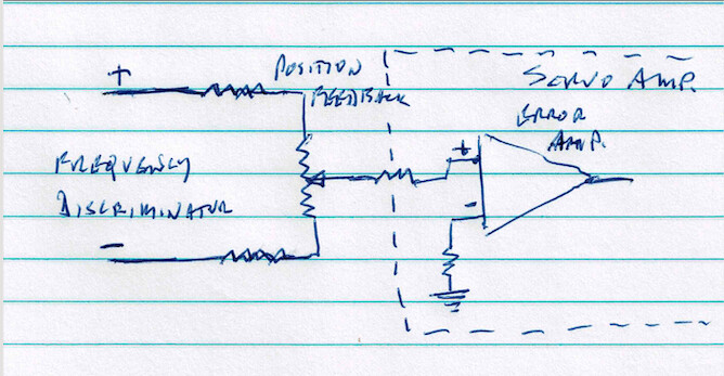
A very simplified part of the positioning sensing

The frequency discriminator supplies 2 voltages, one positive and one negative WRT ground. These are applied to each end of the feedback pot via a couple of resistors which would effectively adjust the actual pot position in the grand scheme of things. The voltage at the slider is applied to the error amp non inverting input, the inverting input is referenced to ground. Thus the amp is looking for zero V at the non inverting input and is arranged to drive the tuning elements and thus the pot to this point.

It is obvious that at some point in the pot travels the slider will be at zero volts and it is this point the amp is looking for.

At some predetermined frequency the 2 discriminator outputs will be equal (I think 8 or 10MHz in this case). As the frequency is changed the outputs will go up or down and would be like moving football goal posts across the playing field. There will always be some point in the pot travel where the slider will be at 0V so the servo will position the mechanism to this point when requested.

So the servo amp is always seeking 0V.

As the discriminator is linear and reactive components have to be moved in a logarithmic manner in practice some alterations to the pot curve are required to achieve correct positioning to tuning components. These particular pots have 5 equally spaced taps on the element to allow the fitting of resistors to modify the pot curve and enable correct positioning. After coarse tuning the system reverts to a fine tuning phase using phase discriminators seeking a 180º phase shift. These last bits concerning taps, resistors and fine tuning would not concern you but I have described for completeness.

I don’t think I mentioned before but all this requires a split power supply, in this case + and - 24V.

You idea of getting a ready made device and adapting to suit is pretty sound even if as you say you construct your own at the end of the day your research and development will have a solid base.

Cheers Bob

2 Likes

Thanks Bob.

Part of me likes the hardware solution. I’ve come across those tapped pots you mentioned before. Wondered what they were when I first saw them. Be hard to find them now especially at a reasonable cost I suspect. Not having any software has its attractions.

But the adaptability of a software approach using shaft encoders and software driven steppers, or PWM control on a DC motor is also very attractive and enables easy fine tuning or even big changes if needed - as long as the mechanics are sound.

The thing about software is that I have to consider what may happen if there is a failure. We will be running from batteries and the likelihood of noise spikes in the supply is very high. Earths can jiggle. If a micro jumps code or resets, what will a drive system do? Will it just stop - steppers just stop if not being actively stepped, but a DC motor and driver could do weird stuff that could damage a gearbox or a person standing too near. So the simplicity of a software solution gets a bit more complicated when the safeguards are designed in. Yes, same issue can occur in a hardware solution but hardware slew rate limiting may be more reliable in noisy conditions. Pot failure could be exciting.

Thanks again for your time and effort Bob. And for looking up that nulling circuit.

Cheers

Mike

2 Likes

Hey @Mike121163,

Welcome to the forum!

This has been a fascinating read, you can really see why Bob mentioned in his first post that you’re venturing into industrial-grade territory! It’s great to see you factoring in safety right from the design stage.

While I don’t have extensive experience with moving robotics, I do have a background in product design for hazardous environments. In a system like this, you’d want to build in a lot of redundancy and fail-safes, such as watchdog timers, clamping diodes, fuses or polyfuses, emergency stop circuits, and mechanical brakes or torque-limiting couplings. Each layer adds protection in case one part of the system fails. Think of it like the Swiss cheese model of safety: each layer has holes, but by stacking enough layers, the holes don’t line up and the system stays safe even if one element fails.

Best of luck with the project!

Thanks Ryan,

Yes, both software and hardware watchdogs and interlocks that disable the motor drivers if a fault condition arises. There will be some particularly valuable cameras and sensors on the platform so I want to minimise the chances of damaging them if the pan/tilt hits the stops at full speed. The main 32m dish antenna at Orroral Valley tracking station in the old days, had controlled density crush pads to protect the dish if it was driven into the mechanical stops so I’ll look at neoprene rubber or similar low rebound pads on this design to limit the deceleration rate in a fault condition. Isolated DC DC power supply modules will help to keep the power clean but “stuff” can still happen!

Swinging a number of kgs around at speed can get exciting so I may just decide to put a kill switch optical perimeter around the platform. That will protect against someone getting fingers trapped in rapidly moving mechanics. Little LASER modules that do this are easy to get and work with and I could build four fold out arms to hold them.

My main reason for engaging in this forum is that I have used CORE before and it seemed they had motors with gearboxes and drive electronics in stock. It’s quite hard to find Australian companies with stock and expertise so I just thought I’d give the forum a go.

And frankly, I just didn’t know how well the CORE motors and control electronics worked. I still don’t but am now more confident that the platform can be designed to accept different motor/gearbox combinations with a simple change in mounting plate so I don’t have to get it all perfect first cut.

I’m retired and it is some years since I have had to do an entire project like this solo. A few years ago, I had 30 plus engineers to do this stuff, but I find I now have to fire up old skills I haven’t used in awhile. Bobs discussion and your points are helping reconnecting old circuits that I haven’t used practically for some years but it seems at least some of them are still there! The whole project is getting quite exciting.

Anyway, thanks for your comments and engagement Ryan! The personnel and equipment safety issues are now more prominent in the design thanks to this exchange.

Cheers

Mike

1 Like

Hi Mike

Very. I think that balance could be useful in relieving stresses when the platform is moved
Although the mechanism is somewhat different where the dish at Honeysuckle was maneuvered by 2 x 180º geared sort of arrangement 90º apart I seem to remember there was several tonnes of lead weights scattered around the structure to balance the whole thing. Seemed to work OK.
Cheers Bob

1 Like

Absolutely. The tilt mechanism will need to be balanced around the horizontal pivot axis. If that doesn’t occur, the stress on the motor and gearbox will change significantly as the tilt cradle moves from horizontal to vertical. A lever arm effect will result, which will try to change the position of the pivot point and the tilt platform will try to rotate around its true centre of mass. At low speed, this is of less importance but rapid movement is different. The specifications on the Chinese platform actually articulate how the balance changes the platform carrying capacity.

The Pan axis likewise. If that is too far out of balance, it’ll try to throw the platform in an arc as the mass rotates. The tilt balance is easy to adjust, but the pan balance may need to use weights as you describe.

I better make sure there is a structure where weights can be added or subtracted easily.

I may need to have a few calibrated weights depending on which cameras are mounted.

Good thought.

Cheers

1 Like