Is it true that under the RTC connector you can put a Raspberry Pi 5 on and off button?

1 Like
Hey Giuseppe, Welcome to the forums!
in regards to your question about the Raspberry Pi those traces are indeed for wiring up an external power button as shown in this GitHub documentation
3 Likes
hi Bailey thanks for the answer then is it possible to connect a button to it I was also seeing the link you gave me thank you so much…another question but the golden holes because one is square and the other is a circle are used to show the more and the less ?
1 Like
The traces are different shapes to identify the positive and negative.
For example, the square trace would most likely identify the ground pin on the Raspberry Pi.
1 Like
Hi Bailey, Guiseppe
Just had a quick search. J5 would seem to be a battery connection and the 2 pads (one square) underneath seem to be connected to J5 pins for possibly a different connector (terminal block??) and if so could be a disaster if you pushed a button while a battery is connected.
Would be a worthwhile exercise to check this (Multimeter to check continuity maybe) before any damage occurs.
Cheers Bob
2 Likes
Hi Guiseppe
It turns out that Bailey is correct. I just found some time and after a LOT of searching the RPi info FOUND IT!!!
“The J2 jumper is located between the RTC battery connector and the board edge. This breakout allows you to add your own power button to Raspberry Pi 5 by adding a Normally Open (NO) momentary switch bridging the two pads. Briefly closing this switch will perform the same actions as the onboard power button.”
The red circle on the pic above made it a bit difficult to see exactly what the tracks are doing. But there you have it. Straight from the horses mouth as the saying goes.
Cheers Bob
3 Likes
Hi Bailey
Thanks for this. Just what I need. I’m upcycling a 2005 iMac G5 case to an HDMI monitor with inbuilt internal RPi5 and want to use the original iMac momentary on/off switch to start up the RPi5. The leads on this switch are pretty fine (0.85mm) so I’m hoping this J2 jumper connection wouldn’t carry too much current for this wire? I presume the current would be tiny? Any thoughts?
Hey @Roger196291,
Welcome back to the forum!
You’re spot on with your assumption: the J2 jumper pads on the Raspberry Pi 5 are designed for a momentary Normally Open (NO) switch and carry only a signal-level current, not power. When pressed, it simply signals the Pi’s power management controller to either turn on or shut down the device, no significant current flows through it.
So yes, your 0.85 mm wires from the original iMac power button will be absolutely fine for this purpose. Just be sure to keep the wiring short and secure to avoid any accidental bridging or interference.
Let us know how the build goes, sounds like a fun one!
Great. Thanks Ryan. Keeping the wiring short will be a challenge. Currently the RPi is destined to be quite a way from the switch. I’ve got quite a few items to accommodate in the case with power supplies, the LCD controller boards, original fans plus controllers, speakers, cables etc. I may be able to relocate the RPi closer to the switch but it would then sit right next to the main 12v power supply for the LCD screen, fans, and the 5v 5A PD power supply module for the RPi. Not sure if that would be a problem. I think I can manage the heat aspect ok but don’t know if interference would be an issue.
1 Like
Hey @Roger196291,
Thanks for the update, sounds like quite the intricate setup inside that iMac case!
Since the Pi’s power button input is just a low-current, low-voltage signal, longer wires can still work well if you take a few simple precautions, like using twisted pair wiring and keeping the switch wires away from high-current or noisy cables.
If you choose to move the Pi closer to the switch, that should also be fine, just make sure there’s proper grounding throughout the case to minimise any interference.
Be sure to upload some photos when you have everything in place, I’m sure more than a few in the community would be keen to see the set-up!
Thanks again Ryan.
I’ve been taking photos throughout the project thus far so will load some up when it all starts coming together properly. Still chasing down a few bits and pieces.
Hi Roger
Just putting my two bobs worth in here.
If this case you mention is metal you could minimise interference problems by taking all DC wiring such as this push button wires out of the case vis “feed through” capacitors.
These are caps that mount through holes in the case with a wire straight through the middle where the internal and external connection is effectively bypassed by this capacitor. A common value used to be 4n7 or in the old jargon 4700pF.
If you are worried about interference all DC connections leaving this case should be done in this manner.
If you wanted to outlay lots of dollars a lot of connectors including the sub D types (DB, DE, etc) have filtered versions. But as I say they come at a price.
This is what they look like

Cheers Bob
Add on: You could also used screened twisted cable, usually AS WELL AS feed through caps. Earth the screen AT ONE END ONLY. Usually at the main grounding point which in your case would probably be this case you mention.
1 Like
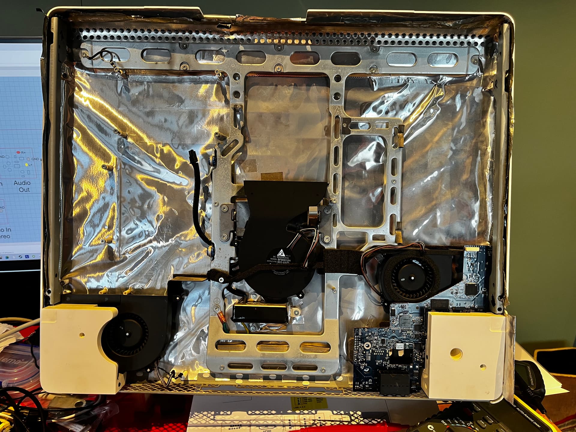
Thanks Robert, The case is polycarbonate. Everything inside was enclosed in emi foil with the wifi attenae installed inside the case but outside the foil shield. The Apple wiring from the switch which went to the logic board is twisted pair. In the image the switch is behind the ivory coloured speaker enclosure at bottom left. i was planning to put the RPi in the space at top centre above the centre fan. Pretty much all other space is spoken for and a good bit of it already installed.
1 Like
Hi Roger
In that case the feed through caps are not going to be of much use are they.
Keep in mind though as this component may be of use in the future. This sort of thing does not get much of a mention in the hobby community it seems
If that foil is aluminium I don’t know how good any shielding would be. Must work OK in this application though or the manufacturer would not go to all this trouble.
Really serious EMI shielding would be STEEL.
Cheers Bob
2 Likes
Has anyone had any success with this?
1 Like
Hi,
Welcome to the forum!!
I can confirm this is a supported feature on the Raspberry Pi 5, not just a community hack. The J2 pads near the RTC connector are intended for a normally-open momentary switch wired across the two pads, effectively duplicating the onboard power button.
I’d sanity-check it before committing by momentarily bridging the two J2 pads with tweezers or a short jumper while the Pi is connected to power. It should behave like pressing the onboard power button. After that, soldering a small momentary pushbutton or an existing case switch across those pads is the usual approach.
The switch wiring only carries a low-level signal, so fine wire is OK.
Liam