Hey,
We are using a RoboClaw 2x30A motor controller to drive x2 24v motors.
We want to add E-Stops to the motors, and have seen that the controller can do this in it.
Below is the diagram that I have found.
What resistor values should I be using for the E-Stops?
And will having them connected to two different pins allow me to control the stop for both motors?
We have two E-Stop buttons (one on each side of the robot we are building), which each has two wires coming from them to the controller.
We had initially set them up with relays, however, want a cleaner way to do it.
We want it so that when either of the E-Stop buttons are pressed, the motors will stop.
At the same time, in the diagram there is a resistor over the switch and diode over the fuse, what values should these be?
We are running x2 12V 100Ah batteries in series (giving 24V, 100Ah)
Cheers,
Hamish
1 Like
You may be referring to S4 and S5. These are not E-Stop switches - they are motor control switches, which would typically be used for end stops or limit switches to remove power to a motor when it is positioned incorrectly. A E-Stop will remove power to the whole unit (except perhaps the cooling fans) so that everything, not just the motors, stops.
The diagram doesn’t make it clear whether SW1 is intended to be an E-Stop or just a main power switch. The reason for the additional coponents, according to RoboClaw is:
When the RoboClaw is switched off or the fuse is blown, a high current diode (D1) is required
to create a return path to the battery for any regenerative voltages. The use of a pre-charge
resistor (R1) is required to avoid high inrush currents and arcing. A pre-charge resistor (R1)
should be 1K, 1/2Watt for a 60VDC motor controller
The resistor wattage and resistance could be adjusted for a different voltage motor. The diode should be rated at 1/10th the maximum current expected, which presumably is what could be the current at the time of switching off. Of course, the maximum current expected at the time of the fuse blowing is much higher than that!
I would take the diagram as showing the main supply switch, not an E-Stop. Your E-Stop switches should be between this switch and the battery. An E-Stop switch is NC, so if you have two of them then they should be in series. A similar diode/resistor pair could be wired across both switches, but in that case the ‘expected’ voltage at the time of switch off should be the maximum current that could be drawn at any time.
3 Likes
Hey,
Thanks for your reply.
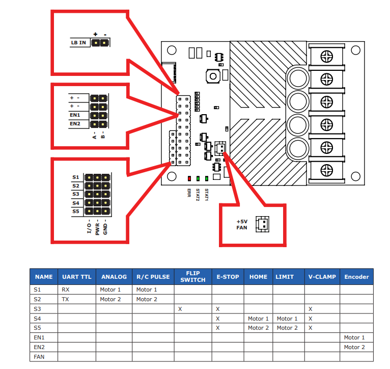
There is a bit of confusion on my side as looking at the manual (https://downloads.basicmicro.com/docs/roboclaw_datasheet_2x30A.pdf), on page 5 (seen below), they say that S3, S4, & S5 can be used for e-stop.
Note: The original diagram seen above is from the link below:
However, then these don’t match?
Regarding the setup for the E-stop, I want to set it up so that the motor controller still has power, however, the power to the motors is stopped.
2 Likes
Hi Hamish
I assume that what is referred to here is an Electronic “limit” switch.This should remove power to the motor in the event of an over run and stop damage.
Firstly for complete safety this SHOULD NOT be done electronically. If the electronics fail Murphy’s Law says it will fail with the motors being driven flat out. Disaster.
The limit switch should be a mechanical switch which when operated removes voltage from the motor completely (the motor only). A switch should be located at each end of travel and operated mechanically by the motor or whatever it is driving.
A couple of hefty diodes are required at each switch. One is arranged so that with the switch operated reverse voltage can be applied to the motor to back the mechanism off the switch and resume normal operation. The other is arranged to be connected across the motor when the switch operates with such polarity as to put a short circuit across the motor thus bringing it to a pretty much instantaneous stop. This will prevent over run which could conceivably go past the switch and re apply power to the motor. An undesirable scenario.
I have a tried and proven circuit I have used many times and posted previously. If you or any one else are interested I can reproduce this here pretty easily so just let me know.
Cheers Bob
2 Likes
Then it’s a motor control input, not an E_Stop. E_Stop is a very specific thing that must meet certain configuration standards. See, for instance:
Emergency Stop Switches
The difference between S3 on the one hand and S4 or S5 on the other is likely in the option available for recovery from a stop. A limit switch is not usually regarded as an emergency condition - it is something that happens in the normal course of operation and can be recovered from by simply stopping the motor and backing up. A 3D printer tests the limit switches like this every time it turns on. This could be the “All stop until switch released” setting (but how the switch gets released is not clear). The alternative that might be the ‘E-STOP’ setting for S3 is “All stop until RoboClaw is reset.” The description doesn’t quite match the table.
2 Likes