Hi Everyone,
I have one of these SD Card adaptors and I’m trying to run the sample code on the same page. I’m using a Pico w for the test.
When I execute the code it sits for over 30 seconds then exits with the following error.
File “sdcard.py”, line 150 in init_card_v2
OSError: time-out waiting for v2 card
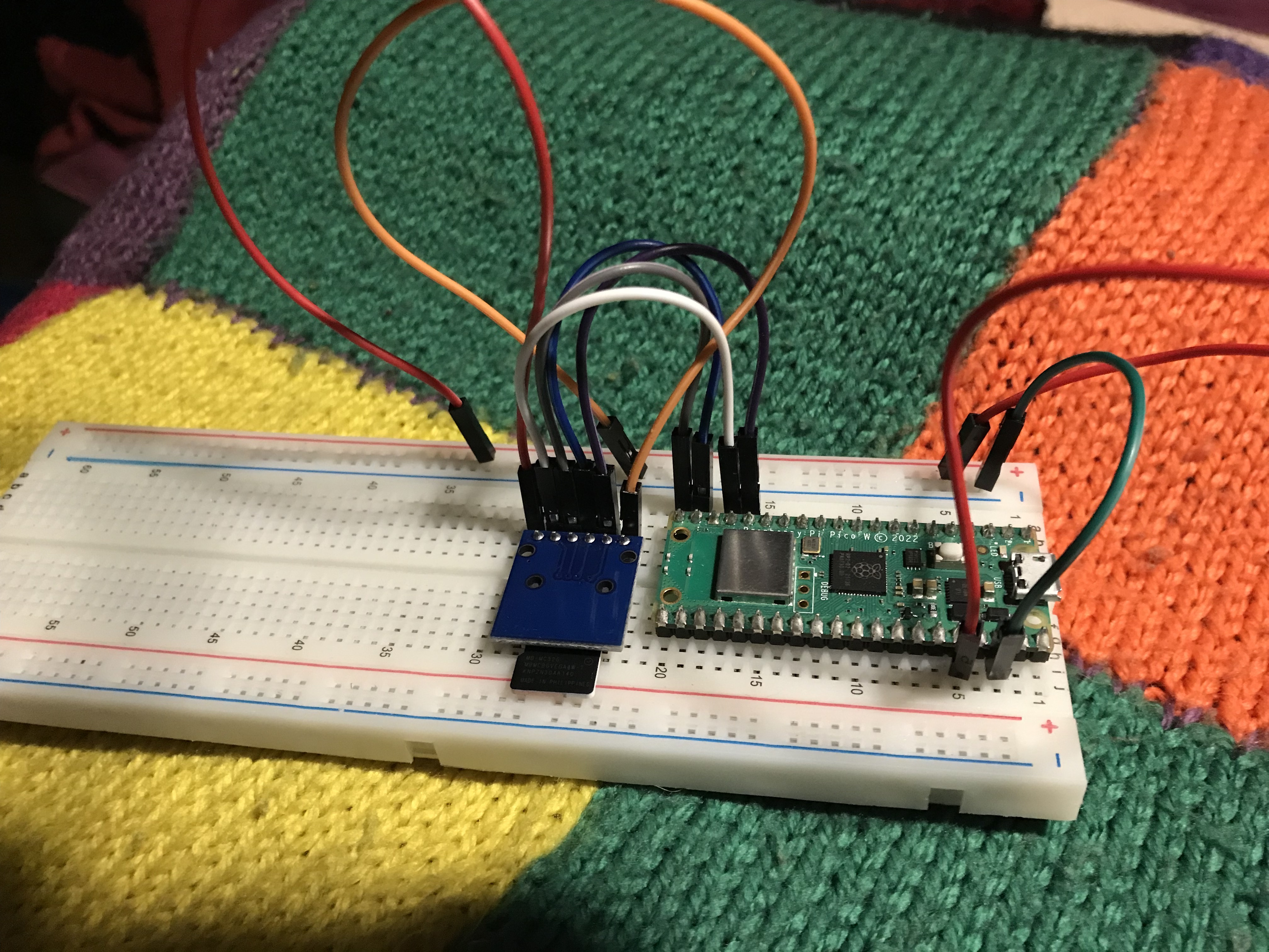
From the description on the above page the pins are numbered left to right when the reader is on my bread board.
1 VCC,3v3 → 3v3(out)
2 CS → GP 13
3 MOSI → GP 15
4 CLK → GP 14
5 MISO → GP 12
6 Gnd → Gnd
This appears to be what is specified in the code but CLK is written as sck. I hope that is correct.
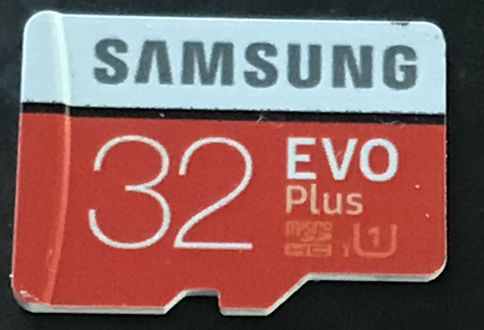
I’m using a 32GB SD card formatted with Fat32 file system with only one file in the root directory. It should be a reasonable quality card (Samsung 32 EVO plus) and it reads and writes no problem on my pc.
I also tried a 64GB card but didn’t really expect that to work.
I’m stuck now on what else to try. Anyone got any ideas?
Checked your pic closely and the wiring looks correct as far as I can tell.
Pin labels on the board would help, but then what can you expect for $1.15.
The code looks ok too with correct pin assignments.
Maybe try swapping the MOSI & MISO wires, have found them to be labelled wrong in the past.
Or it could be a dud board being so cheap.
Cheers
Jim
EDIT: It might be worth it to look at the Makerverse SD card reader/writer or something else.
Hi James,
The code is on the product page.
The required library is linked on the product page. It’s just one file. The only thing have changed it to add debugging stuff. I’ll have another look later today. I’ll also try another sd board it’s just the waiting for the mail man that is a bit of a drag.
Edit
I have swapped the wires on mosi (pin 15) and miso (pin 12) and the error when I ran the test is “OSError: no SD card” so I swapped them back.
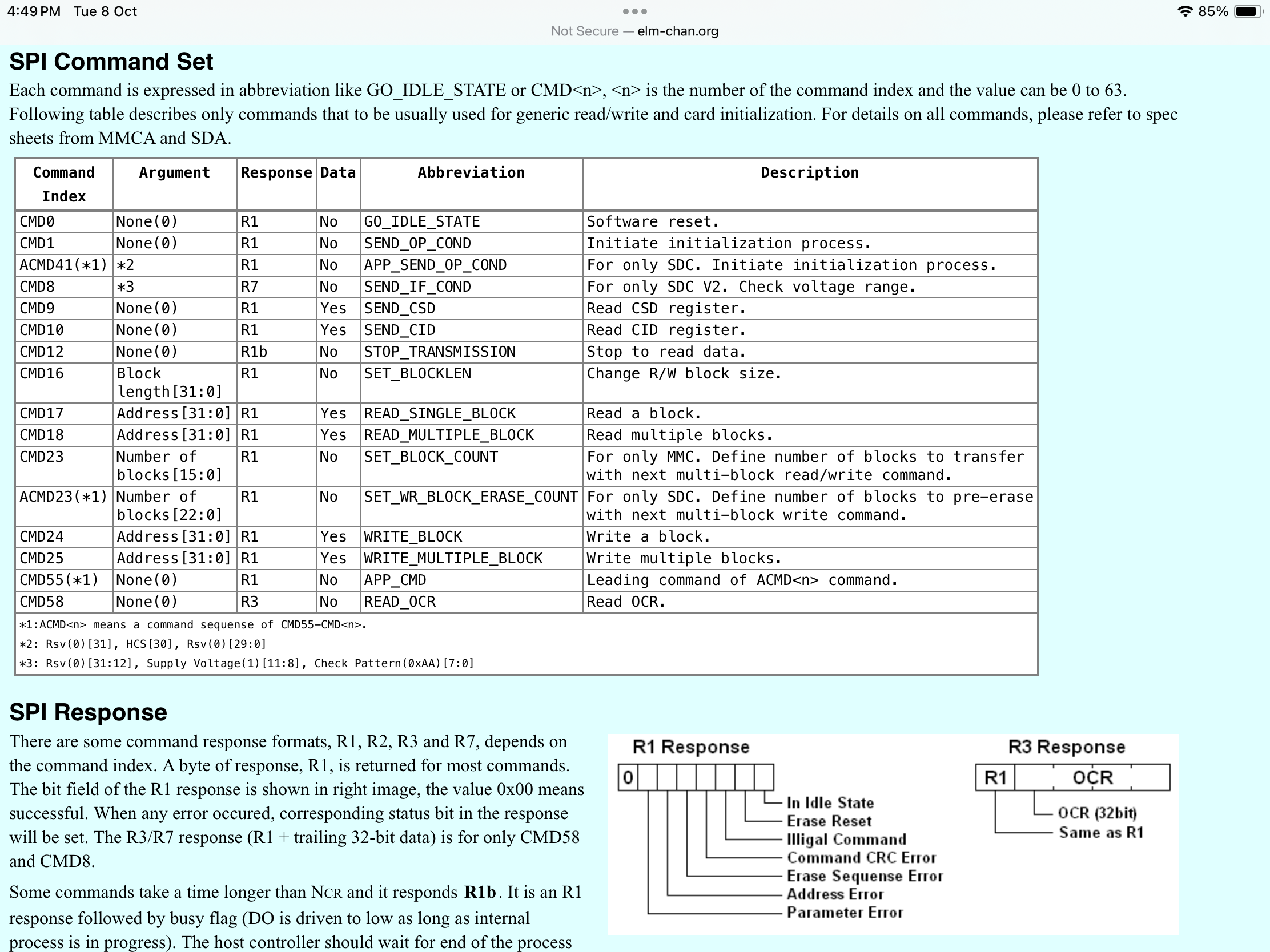
In the library sdcard.py I see lots of commands being sent to the SD card within the method init _card_v2(self).
In one command it expects the result 0 but it receives the result 5
If self.cmd(41, 0x40000000, 0) == 0:
I’m not sure where to find what these commands and results mean.
It basically tests this command 1000 times before it times out.
Thanks
David
PS The fact it returns a 5 and not an error tells me the problem is likely to be in the code. More debugging required. If/when I find the problem I’ll post the solution and how I got there.
I doubt anyone here will crack this one unless they can reproduce the problem on their own device.
I found some great details here on how the conversation between the host computer and the SD card works. Some of the logic is a bit odd, like if it doesn’t understand “this command” then it must be a V1 card. http://www.rjhcoding.com/avrc-sd-interface-3.php
Basically after the card receives the ACMD41 cmd it will return a 1 if the card is idle and return a 0 if it’s ready. Keep sending the command until a 0 is returned. My card returns a 5. I can’t find what that means.
I have a 16 GB card on order to see if that will do anything different.
Hopefully that will rule something out.
David
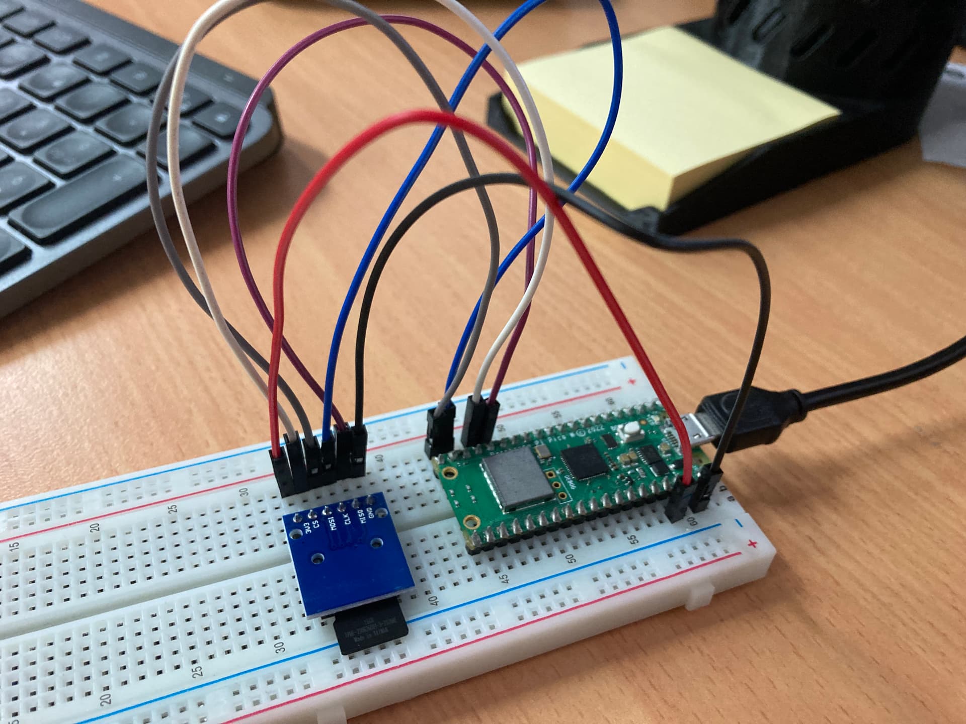
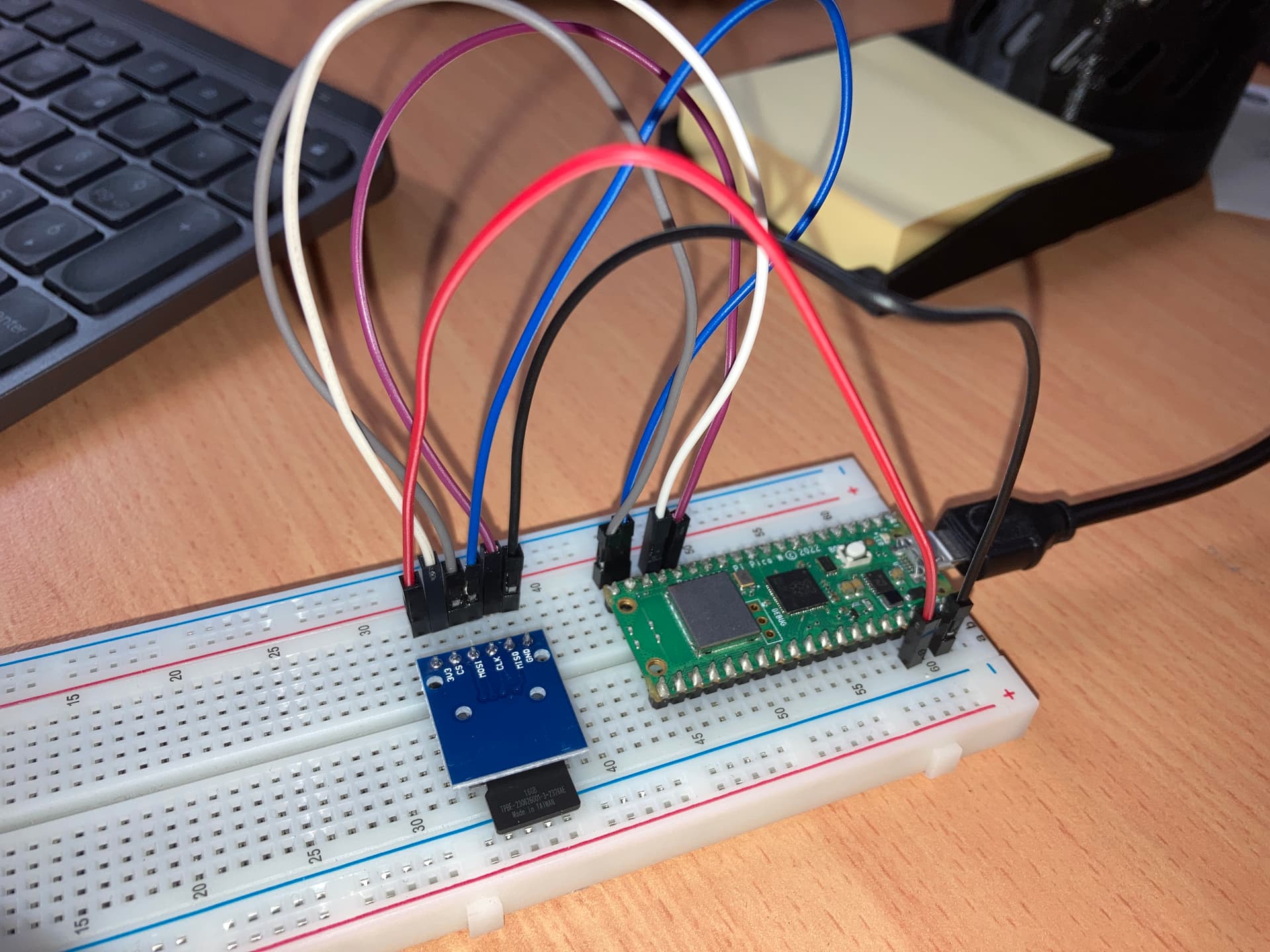
This is a bit of a puzzling issue. Your conclusion that the response of 5 may be a cause or symptom of the issue with the SD card seemed correct at first. I used one of our off-the-shelf models to test this exact code, and print the response from that function.
My SD card setup is identical to yours, however the SD card is successfully written to, and I also receive “5” as the output to the function. I can send you pictures of this setup if you would like.
My thoughts for the 5 output are that it could be related to number formatting. I primarily code in C so my immediate assumption when I see a weird number is that it is meant to be in a different format (binary or hex for example). But at the end of the day I am not sure.
You say that your code is identical to the example code, it may help to send your version over. I always get someone to double check my code in this case, since you seem to have ruled everything else out, but you may be right that the board is just a dud.
Hi Zach,
Ok here is the code I’m testing with and the debug output Im getting.
I know it seems like overkill but this is how I debug all my code. sdcard.zip (4.6 KB) debugLog.zip (2.3 KB) sdCardTest.zip (2.1 KB) (Updated) debug.zip (3.2 KB)
sdcard.py is the library with the added debug output.
sdCardTest.py is the test code from the product page with added debug output.
The output is to the console and to a file named debuglog.csv
The 5 in the cmd response could be some bit masked thing but the code clearly expects a 1 which makes it loop and try again and a 0 is success.
I’m keen to hear what you think.
David
When I tested the basic test code yesterday (on the website, without your debug code), it was working just fine. I tested it again this morning and nothing has changed.
I was going to test your code but I believe I am missing some libraries, as I am getting errors importing. Originally the error was with “import constants”, after installing the constants library it is throwing another error. Could you send a list of libraries/dependencies you’re using? Just saves me the trouble of going through them one by one. Thanks!
One more thing, I noticed in SDCardTest.py that you are still using/uploading the ADC sensor reading. This should work perfectly fine, though in my test code I changed this to an integer value to eliminate some errors, could be worth trying. Likely not the cause of the issue, but who knows, the 0 reading could be somehow decrementing and overflowing. Doesn’t normally happen in python but worth a shot.
Hi Zach,
My mistake with the code. I removed the requirement for my constants.py then uploaded the old file.
Here is the correct one. I’ll also try and edit my post above to correct that file as well. sdCardTest.zip (2.1 KB)
The ADC sensor thing is after the init procedure has already failed so that’s not the problem.
I’m a little confused how you say you are running the same code as me and receiving the same “5” response yet your code succeeds.
Clearly the only success response is a 0.
I’m keen to see your debug output when you get my code to run.
Thanks
David
Hi Zach,
You must have read my last message with an optimistic eye
It’s not working I just fixed the problem that stopped you from running my debug code.
As i said im curious how your works when you also receive the same 5 return code when the only valid code is a 0
David
That was me, I just hadn’t realised that I wasn’t quite signed in.
I’ve had a look at your code and after some small tweaks I think having it at least prints what it is saving. I used 2 different cards. The first one was problematic hence the high count in the debug counter. I am saving values to the card, and the counter hasn’t gone up since.
After importing libraries for ADC and time into your test script, I also changed this line in your edited SD library from
_CMD_TIMEOUT = const(1000)
to
_CMD_TIMEOUT = const(3000)
At 1000 it wasn’t detecting a card, it can probably be lower but this worked for me. SDPicoW.zip (6.1 KB)
Hi Jack,
That’s interesting, I notice in the debug log you sent in the zip, that your Sd card successfully initialises (returns 0) on the second attempt of cmd 41, on line 25 of the debug log.
So I copied your updated code to my pico and let it run all 3000 iterations with the same 5 result which I was kind of expecting.
Do you have the same Sd card board that I’m using?
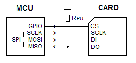
I notice this text from the link above and I’m not sure which bits I should be testing. Especially the bit about the pull up resistor or which mode is being used.
Extract…
SPI Mode
Minimal configuration for SPI mode
This document describes about SPI mode to control the MMC/SDCs. The SPI mode is an alternative operating mode that defined to use the MMC/SDCs without a native host interface. The communication protocol of the SPI mode is slightly simple compared to its native operating mode. The MMC/SDC can be attached to the most microcontrollers via a generic SPI interface or some GPIO ports. Therefore the SPI mode is suitable for low cost embedded applications with no native host interface is available. There are four different SPI modes, 0 to 3, depends on clock phase and polarity. The SPI mode 0 is defined for SDC. For the MMC, it is not the SPI spec, both latch and shift operations are defined with rising edge of the SCLK, but it seems to work at mode 0 at the SPI mode. Thus the SPI mode 0 (CPHA=0, CPOL=0) is the proper setting to control MMC/SDC, but mode 3 (CPHA=1, CPOL=1) also works as well in most case. A pull-up on the DO cannot be omited, or some cards will fail initialization process.
Update:
I tried enabling the internal pull up resistor on GPIO 12 (miso) like this in line 14 sdCardTest.py
Before
spi = SPI(1,sck=Pin(14), mosi=Pin(15), miso=Pin(12))
After
spi = SPI(1,sck=Pin(14), mosi=Pin(15), miso=Pin(12,Pin.IN,Pin.PULL_UP))
But that didn’t make any difference.
I’m running out of ideas now. Next I’ll try a different SD card when it arrives in the post
If that doesn’t work I’ll try a different card adapter.
David
This issue keeps getting weirder! Jack’s code output is 0 as it successfully initialised the card as you mentioned. I agree that it doesn’t make a whole lot of sense but I can guarantee you my code was outputting a 5 but still successfully initialising the card. Jack tried multiple cards and multiple boards (all the same one, and identical to yours) and had it successfully writing with both a 5 and a 0 (on two separate boards I believe). He also received a 275 as the output at one point, but that unsurprisingly was not working correctly. I’ll see about running that new code and getting the debug uploaded.
I may be able to try the aforementioned pull-up resistor on the MISO pin. Stay tuned.
Hi Zach,
I’d be interested to see how your process is getting past this bit without returning a zero from cmd 41 as everything else is a timeout error.
The debug output should show the programs execution path.
Well my new San Disk Ultra 16GB SD card worked but I don’t understand why.
The CMD 41 succeeded with a result 1 not 0.
I removed the demo sensor stuff and simply wrote “Hello World” to the SD card no problem. Not sure why the original SD card is not compatible but it doesn’t really matter.
This is the non functional Sd
Look at that. I was using Zach’s setup just with different SD cards. It seems this debugging code is great at picking out errors with our cards more than the code.
Glad to see you’re saving data. Hopefully your project travels more smoothly from here
        if(DEBUG >=1):
            initResult1=self.cmd(55, 0, 0) # Application Specific Command coming up
            initResult2=self.cmd(41, 0x40000000, 0)
            debug.debug(DEBUG, "init_card_v2()", "CMD 55 Init Result1="+str(initResult1), LOGTOFILE)
            debug.debug(DEBUG, "init_card_v2()", "CMD 41 Init Result2="+str(initResult2), LOGTOFILE)

        self.cmd(55, 0, 0) # Application Specific Command coming up
        # Card returns 'in_idle_state=0' when card is ready.
        if self.cmd(41, 0x40000000, 0) == 0:
            self.cmd(58, 0, 0, 4)
            self.cdv = 1
            # print("[SDCard] v2 card")
            return
    raise OSError("timeout waiting for v2 card")
I execute CMD 41 and out put the result
Then I execute CMD 41 again for the “if” statement.
The first time it returns a 1 but the second it must return a 0.
That explains it
David