James46717 just shared a new project: "Arduino Audio Recorder with Playback"
Introduction
This project started with an idea, as most projects do. I wondered if I could use the Arduino UNO to record audio and play it back. I wanted something to amuse the grandkids. They would press a button, say something and the device would then repeat what they had said.
Parts used in this project:
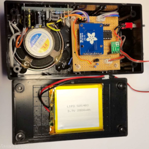
Atmega328p with Arduino Bootloader
3.7V LiPo 2000mAH
Electret Microphone Amplifier
MicroSD Card Breakout Board
Pololu 5V Step-Up/Step-Down Voltage Regulator S7V7F5
Single Push Button Switch
LED Tri Colour Single Anode
In my search, I found many people had used Arduino devices to digitise or playback audio; so I had confidence it might be worth a try.
The starting point for me was:-
APC magazine - Arduino Masterclass
- Project #18 - Digital Audio Recorder v2.0
- Darren Yates - 11 April 2014.
Modifying the code to suit my purpose I was able to record audio that played back on a PC with reasonable clarity. Previously, I had successfully read and written files to an SD Card using the SdFat Library by Bill Greiman. This is an excellent library for accessing SD Card files.
Outputting the audio from the ATMega328P proved much more difficult. After trying a number of options which only produced distorted audio, I was ready to give up.
I posted on the Core Electronics forum the audio recording part.
Stephen replied with a link to
Maks Surguy’s blog on Innovation, IoT and Laravel – 1 Feb 13
How to play WAV audio files with Arduino Uno and MicroSD card - Maks Surguy’s…
I checked it out and examined the TMRpcm.h library in detail, which was being used. The library was not suitable for what I was doing as the audio recording routines were not fully developed. But it did give me a good insight into what I needed to get my device working.
Overall this project has given me a better understanding of the ATMega328P registers and audio wave files.
Read more
1 Like
This is a very well documented project James! Great work!
Hi,
Awesome project!
Could you help me translate this for arduino pro mini? I’m new to arduino and is a little over my head…
Apologies for delay in reply. I have been busy with a Robot Cart and other things.
This was not a simple project. It was an exercise in how far could I stretch the ATMega328P. There are many devices that record and playback short audio clips for much less than the cost of this project.
-
Suggest using the 5V/16MHz Pro-Mini, which would be similar to the ATMega328P I used. The reason is the audio input and output depends heavily on the clock frequency. The software is configured to use a 16MHz clock. With a lower clock the digitization values would be different and the audio quality would most likely suffer. It was only when I doubled the rate that the output quality was reasonable. The first efforts were very distorted audio output but the input file played ok in Audacity.
-
Writing the software buffer to the SD card must be accomplished before the next buffer is ready. At 16MHz this was achieved ok, at 8MHz it might not be.
-
Most Important Point !!! The AREF pin of the ATMega328 is not available on the Pro Mini pins. You would have to hack the board to get to it, possibly damaging the board if not careful. You might be able to solder to the chip capacitor, very carefully, with a very fine tipped soldering iron. But I would not risk it. This pin is important because it changes the Analog reference voltage (2.5V) to be closer to the MIC output (2vpp). This allows for a better range of digitized values. At 5V reference the audio quality would be less. Testing showed this to be the case.
Except for the points above you shouldn’t have to change the software for the Pro Mini, it uses a SMD version of the ATMega328P. My device was a 28Pin Dip version (easier for me to work with). The AREF level is the biggest problem.
I would be interested to hear how you go.
Cheers
Jim
1 Like
Hello, I’m in charge of recording as an aduino Uno in my company. I found your great project and I received the program and entered it, but it didn’t work. I used a microphone called max4466 and Arduino Uno. When i was recording and Looking at the file, but the sound was not recorded. Can you help me?
Hi,
I had a brief look at the device you are using, it is a little different than the one I used.
The Electret Microphone Amplifier - MAX9814 SKU: ADA1713, was chosen because it has Auto Gain Control and the ability to set the maximum gain level. It has a DC offset of 1.25V which made it ideal for connection to the ATMega328P Analog input with the reference set to 2.5V.
The Electret Microphone Amplifier - MAX4466 SKU: ADA1063, has manual gain control, which would be hard to set with the micro trim pot. It also has a DC offset of VCC/2. If you are using a 5V supply and gain set to 2Vpp; then the signal would vary from 3.5V to 1.5V. It would be clipped by the Analog input.
In building this project I went through many testing stages. The timing is critical, the micro clock must be 16MHz.
The circuit could be redesigned to use the MAX4466, the external reference diode would need to be removed and the reference set to AVcc as per the ATMega328P datasheet. The lack of auto gain control may lead to some distortion with varying audio levels.
Suggest you establish a staged approach.
Is the MAX4466 producing audio ?? I tested this with connection to a small headphone ear piece through a capacitor to decouple the DC. You could then vary the gain and hear the change.
Is the ADC actually working ?? Stop the program and send the buffer to the serial port.
Are the files being copied to the SD ?? What data is in the files ?? Does the file run ok ??
Does it sound ok ??
This is where Audacity and the Hex editor help me greatly in determining what was not working.
Without more information it is hard to say what is wrong. The differences of the Mic Amps are definitely an issue.
Regards
Jim
1 Like
Thank you for your reply. I understand what you said. But I’m not confident of reassembling the circuit. Therefor, the entity decided to purchase max9814. I’ll try again and get back to you 
1 Like
I changed the microphone to max9814 and supplied 5V to Gain and VDD. max9814 OUT was then connected to A0. And executed your code. I played the recorded wav file on my computer, but there was no sound. Is it because SD card module is different from your module? help me…
Hi,
There are a number of things you can check.
-
I am using a Windows 10 PC. The recorded files played ok with Windows Media Player (old version) and Groove Music (Windows 10 music player).
-
While getting the program to work, Audacity proved invaluable. Link below. It allows you to see what is in the audio file and if its a valid audio file. (free open source software)
https://www.audacityteam.org/
-
Another program that helped was HxD Hex Editor. It allowed me to check that the right header information was being saved to the file. (freeware)
https://mh-nexus.de/en/hxd/
-
If the SD Card Module uses the SPI interface, Digital pins 10 (SS), 11 (MOSI), 12 (MISO), 13 (SCK); it should work ok. But the SD library might not work with it, depending on the module. If you can tell me which you are using I could do some checking. I assume you are using the Arduino IDE and that all the libraries are up to date.
-
Questions.
How many bytes is the file saved to the SD Card ? If its zero it means no data is being saved.
What does the header of the file look like in HxD Hex Editor ? The data should be like the table below.
What does the file look like in Audacity ? This can be very helpful in determining why it is not working.
The image below is a Audacity screen shot of an actual file I recorded. You can clearly see the audio wave form. If you get a straight line, it means no audio is being recorded. Initially I was getting very low level audio, hard to hear in a wav file player but easy to see in Audacity.
I intend to copy the program from the Core Electronics web site and load it into my device. Just to see if something went amiss when I uploaded it to Core as a project. I will do this in the next day or two and let you know how it goes.
Regards
Jim
| Address |
Bytes |
Data |
Description |
|
| 00 01 02 03 |
4 |
52 49 46 46 |
“RIFF” |
|
| 04 05 06 07 |
4 |
BC AF 01 00 |
File Size, LSB. 0001AFBC = 110,524 |
|
| 08 09 0A 0B |
4 |
57 41 56 45 |
“WAVE” |
|
| 0C 0D 0E 0F |
4 |
66 6D 74 20 |
"fmt ", note space at end |
|
| 10 11 12 13 |
4 |
10 00 00 00 |
Size of rest of ‘Chunk’ up to “data”. 2 + 2 + 4 + 4 + 2 + 2 = 16 |
16 |
| 14 15 |
2 |
01 00 |
Audio Format. PCM = 1 |
|
| 16 17 |
2 |
01 00 |
Number of channels. Mono = 1, Stereo = 2. |
|
| 18 19 1A 1B |
4 |
40 1F 00 00 |
SampleRate = 8000, 44100, etc. 00001F40 = 8000 |
|
| 1C 1D 1E 1F |
4 |
40 1F 00 00 |
ByteRate = SampleRate * NumChannels * BitsPerSample / 8 |
|
| 20 21 |
2 |
01 00 |
BlockAlign = NumChannels * BitsPerSample / 8 |
|
| 22 23 |
2 |
08 00 |
BitsPerSample 8 bits, 16 bits |
|
| 24 25 26 27 |
4 |
64 61 74 61 |
“data” |
|
| 28 29 2A 2B |
4 |
98 AF 01 00 |
Data Size, LSB. 0001AF98 = 110,488 |
36 |
| 2C to 01AFC3 |
|
PCM wave data |
|
|
***** Update: *****
Found an error in the code uploaded to Core Electronics projects.
First line #include should be #include <SdFat.h>
Don’t know why this was not there. This is an excellent library by Bill Greiman. The standard SD library will not work. Search for sdfat in the Arduino IDE library manager.
First of all, this is my sd card module. name is: SparkFun Level Shifting microSD Breakout
Thank you for answering first. In fact, I already included #include <SdFat.h>. Because you mentioned it already. But again, it didn’t record again.
And the first picture is the picture of the recording file in HxD. The header of the file looks normal, but there is only FF in the sentence where the microphone input should be recorded.
The second picture is from Audacity. No waveforms are visible.
The third picture I wanted to show you was a byte.
Hi,
Well this is embarrassing !!!
I think I have found the reason its not working for you.
The schematic shows Analog input A0, but the program code uses Analog input A5.
I was measuring voltages on the device I built and found the 1.25VDC from the Mic Amp on pin 28 (A5) not pin 23 (A0). I then remembered the intention was to use A0 but in construction it was more convenient to use A5 and I forgot to change the schematic. Sorry, My bad !!!
If you connect the Mic Amp output to A5 rather A0 it should work.
Alternatively you could change the program code.
In void Setup_Timer_1_2_and_ADC() { the line ADMUX = 0x25; selects A5.
Change it to ADMUX = 0x20; and it selects A0.
I will leave it up to you what you want to do.
Appologies for the discrepancy between the program code and the schematic.
The FFs in the file are because A0 is at zero volts. I now remember this happened to me when I first altered the wiring. At that time I should have changed the schematic. I have now done this on my PC, but the Core Electronics page is still wrong. I will ask them to change it.
Regards
Jim
Can do, just shoot us an email 
First of all, it was very helpful to proceed with the project. I finally succeeded in recording my voice and it was saved well in my sd card. Thanks to this, the progress of the project is more than 50%. But we’re in trouble again.
In fact, we were recording voices and trying to get frequencies and decibels at the same time. But is it impossible for Arduino to get frequency and decibels while recording?
I tried this part, but I failed. So I came up with a different way. Obtains the value of the analogRead function from the wav file. Is there any way you can get it?
Or is the above mentioned simultaneous operation possible?
Hi,
While the Arduino is recording it does not have much time to do anything else, it is not a very fast processor. Timer 2 interrupts every 64uS to start the ADC which takes 6.5uS to convert the analog level. The main loop checks for a button press to end recording and to write the buffers when they are full (256 bytes). I haven’t done any rigorous calculations but I suspect there is not much time left to do anything else. I was actually surprised it worked at all.
An audio wave form such as voice contains many frequencies. You could perform analysis of the wav file to find frequencies, but that is beyond the scope of the Arduino. It would involve significant processing of the data.
The decibel level could be calculated but once again it would be beyond the scope of the Arduino.
Audacity can display the waveform as dB and as a spectograph.
The answer to your questions are:-
Yes, it can be obtained for the wav file using something like Audacity.
No, simultaneous operation is not possible.
Regards
Jim
I checked the pcm data values stored in the WAV file using the HXD you recommended. I found out that this pcm data makes sound. Can you tell me how the ADC works for Timer 2?
Finally, what I want is the relationship between PCM data and analogRead function values!!
The relationship between PCM data and anologRead function values is the core of our remaining project. Because we got frequency and decibels from analogRead.
Hi,
I will try to explain.
Each value in the wav file represents the voltage level detected on the Analog pin at a specific time.
PCM is the representation of this voltage as a digital number. With 10 bits you have 1024 different values that can be represented. In the case of this device only 819 values are used because the input voltage maximum is 2VPP and the analog range is 2.5V. 0.25V either side is never used. The number of values is even smaller as we are only using the upper 8 bits. The Arduino is not fast enough and does not have enough memory to use all 11 bits for audio recording.
Timer 2 is set to interrupt every 64us (15625KHz). Every time it interrupts the ADC is started and takes 6.5uS to complete the analog to digital conversion. This digital value is then saved to the buffer.
Timer 2 is essentially a counter that increments at the Arduino clock rate (16MHz) divided by 8. When it reaches a certain value, an interrupt is generated and the counter is set back to zero and starts counting again.
This code sets up Timer 2. OCR2A contains the top value of the counter.
 void Setup_Timer_1_2_and_ADC() {
  TCCR2A |= _BV(WGM21);
  TCCR2A &= ~_BV(WGM20);

  TCCR2B &= ~_BV(WGM22);
  TCCR2B &= ~_BV(CS22);
  TCCR2B |= _BV(CS21);
  TCCR2B &= ~_BV(CS20);

  OCR2A = 127;
This code is interrupt service routine, where the ADC is started and the value saved. ADCH has the 8 bit digital value after analog to digital conversion.
ISR(TIMER2_COMPA_vect) {

  if (RecordActive) {
    sbi(ADCSRA, ADSC);                  // start ADC sample
    while(bit_is_set(ADCSRA, ADSC));    // wait until ADSC bit goes low = new sample ready,
                                        //           about 6.5uSecs at 2MHz ADC clock
    ByteCount++;
    bufByteCount++;
    if (bufByteCount == BUF_SIZE) {
      if (! Buffer) { Buffer = true; } else { Buffer = false; }
      bufByteCount = 0;
    }
    if (! Buffer) { buf00[bufByteCount] = ADCH; } else { buf01[bufByteCount] = ADCH; }
  }
Direct register access is used because the analogRead() function is too slow to produce good quality audio. The Arduino IDE compiler knows the register and bit names such as ADCH, OCR2A, ADSC etc. It converts these to the actual register addresses and bits when it makes the program code.
Regards
Jim
Thanks James for the detailed response.
Does the AREF have to be supplied by the arduino board?
Isn’t there an electronic workaround to that? For instance use an amplifier of some sort to create a 5V output?
Thanks again for your help!
Gil
Hi Gil,
Have looked in more detail at the Pro Mini.
If your version uses an ATMega328P it should run the program code ok. If it uses the older ATMega168 then it wont. Not enough RAM. This number will be on the front of the chip.
The rest of this discussion will focus on the 328P.
The reference voltage for the Analog to Digital converter can be one of the following:
- VCC
- Internal 1.1V
- External voltage. (2.5V in this case)
The Mic Amp I used in my circuit outputs 2Vpp on a DC level of 1.25V. An external reference of 2.5V places this signal right in the middle. Best place for audio ADC. The Pro Mini does not provide an external connection to the AREF pin, even though the pin is available on the chip. (they probably ran out of space and pins in the design of the Pro Mini) Attaching a reference diode and resistor to the pin of the chip would not be an easy task and could kill the Pro Mini. There is a chip capacitor attached to the pin which could be removed allowing easier access because the pad the capacitor is soldered to is bigger. But this would also be difficult.
Alternatively you could use a different Mic Amp. The one that YU1678 initially used (see conversation above) might work for you.
It has manual gain control, but the DC level is VCC/2. You could use VCC as the reference. No need to solder any components, just change the software.
In the following function where ADMUX = 0x25 change this to ADMUX = 0x65. This selects the reference as VCC.
void Setup_Timer_1_2_and_ADC() {

  ADMUX = 0x65;
Please note that in conversation with YU1678 I discovered an error in the program code and schematic. These have now been fixed on the Core Electronics web site.
Hope you have success.
Cheers
Jim
PS I dont have a MAX4466 board to test. I originally chose the MAX9814 because it has automatic gain control and seemed like it would produce better audio.
1 Like


