I’m having trouble with this display, but I see reviews which must indicate some have it working. I am trying to connect it to a seeed xiao nrf52840 sense with a few other i2c devices. I can run a scan sketch and detect a picodev bme280 at 0x77 and a stemmaQT rotary encoder at 0x36, but cannot get anything comms from this display. I’m noting that it says 0x7A and 0x7B on the back, which through a quick google search seems to show that the address is outside the regular i2c range? I’ve also tried a number of generic sketches that use address 0x3C or 0x3D all with no success. I’ve triple checked my wiring and cannot see any issues? I’ve used the pins on the short side. Any guidance would be appreciated.
Did you try address 78 (print sometimes can make B and 8 look the same), on the core image on one I found on aliexpress, both look to be 0x78 could be the default address.

Side note: in I2C any 7 bit address should be valid.
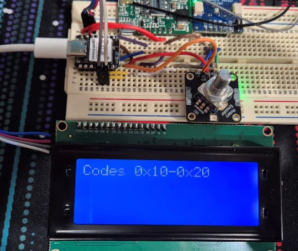
Further info, I am able to detect a 2004 LCD using a simple sketch that scans for all active addresses:

At 7:30 you can see with the alternate screen connected, I detect 0x27. And an example sketch works. The scan at 7:46 with the SSD1309 display connected detects nothing.

I ordered 3 of these, and I’ve tried a second one in case the first was faulty. If I’m missing something obvious, please let me know.
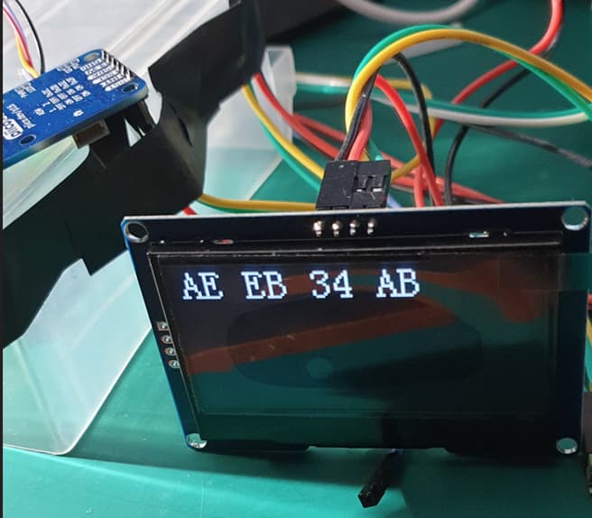
I’m scanning all the way to 7F:
  for (uint8_t addr = 0x08; addr <= 0x7F; addr++) {
    Adafruit_I2CDevice dev = Adafruit_I2CDevice(addr, &Wire);
    if (dev.begin()) {
      Serial.print("Device found at 0x");
      Serial.println(addr, HEX);
      found = true;
    }
  }
Google AI says:
I2C address
0x78is generally considered a reserved address in the standard 7-bit I2C addressing scheme. While it might be used by some devices, it’s often avoided because it’s part of the range (0x78-0x7F) reserved for 10-bit I2C addressing or other special functions. If you encounter a device claiming to use0x78, it’s best to verify if it’s using the standard 7-bit addressing or if it’s a 10-bit address or another I2C function
Hi @lwsjss
Welcome to the forum!
Are you able to post the code that you’re using to run the display? This will give us a better idea of what exactly is going on.
Another thing to check would be that the jumper wires you’re using have continuity between both ends.
Hi Dan,
I’ve tried multiple sketches and worked my way back to just searching for the address using this code:
#include <Adafruit_I2CDevice.h>
#include <Wire.h>

void setup() {
  Serial.begin(115200);
  while (!Serial) {
    delay(10);
  }

  Wire.begin();
Serial.println("Starting:");
  bool found = false;
  for (uint8_t addr = 0x08; addr <= 0x7F; addr++) {
    Adafruit_I2CDevice dev = Adafruit_I2CDevice(addr, &Wire);
    if (dev.begin()) {
      Serial.print("Device found at 0x");
      Serial.println(addr, HEX);
      found = true;
    }
  }

  if (!found) {
    // Stay silent
  }
  Serial.println("Done");
}

void loop() {}
I detailed its output in the post above, the display does not respond like other components do. I’ve tried running the test without the other components attached in case there was a clash of addresses, and still nothing. I’m confident that the wiring is correct… I’ve tried it both direct into the bread board, and via the wires pictured above into both the short and long side headers. The cable clearly works as the 2004 has no issues.
As far as getting it to run… I’ve tried multiple online examples, including the below. I’ve tested addresses 3C, 3D, 78, 7A, 7B and all do nothing. I’ve also tried the same with Wire.begin() commented out.
I’m confident now that the issue is something to do with 10 bit i2c addressing, which goes beyond my ability to fault find.
#include <Wire.h>
#include <Adafruit_GFX.h>
#include <Adafruit_SSD1306.h>

#define SCREEN_WIDTH 128
#define SCREEN_HEIGHT 64

#define OLED_RESET    -1  // Reset pin (not used)
#define SCREEN_ADDRESS 0x3C  // Common I2C address for OLED displays

Adafruit_SSD1306 display(SCREEN_WIDTH, SCREEN_HEIGHT, &Wire, OLED_RESET);

void setup() {
  Serial.begin(115200);
  delay(10000);
  Wire.begin();
Serial.println("SSD1306 starting");
  if (!display.begin(SSD1306_SWITCHCAPVCC, SCREEN_ADDRESS)) {
    Serial.println("SSD1306 not detected! Check wiring.");
    while (true); // Stop execution
  }

  Serial.println("SSD1306 detected!");

  display.clearDisplay();
  display.setTextSize(2);
  display.setTextColor(WHITE);
  display.setCursor(10, 25);
  display.println("Hello, World!");
  display.display();
}

void loop() {
  // Nothing here, text stays on screen
}
Apologies if this is too obvious… but have you stuck a voltmeter on the board to confirm it is actually powered? Or does it have an LED?
I’ve hit issues with other I2C displays if the I2C connector is not making good contact.
Will be interested in the results… I could use one of these in my current project.
Cheers,
T.
1 Like
Not directly, and im away from my desk at the moment, but the same cables were able to power the 2004 LCD without issue. I’ve also had it directly into the bread board, power isnt the issue ![]()
I have tested for voltage at the pins and it is reading correctly. I’m stumped, it must be something to do with 10 bit addressing.
Maybe, but looking around I dont think so.
I think that maybe its “stating the shifted” address byte.
But you did a full scan and did not find anything. so kinda rules it out as well … mmmm
My thought was more based on
0x78 => 0b01111000
if we right shift we get 0b00111100 => 0x3C
i.e. normally we have our I2c address, (7 bits) and left shift 1 bit as the last bit becomes the R/W bit.
src: http://www.lcdwiki.com/res/MC154GX/1.54inch_OLED_SSD1309_IIC_Module_MC154GX_User_Manual_EN.pdf
while not the same display, its the same driver chip.
Based on the following image the 7 bit address would be 0111100 (0x3C) but before that in the document it was talking about 0x78 as the default address.
Of couse the image example could be wrong, but interesting)

Hi @lwsjss
If you wanted to shoot over an email to our support team on support@coreelectronics.com.au with your order number we can get this sorted out for you.
I got mine working today after they arrived.
Lots of reading but found the source of the issue.
There boards seem to have an SPI bug.
I am using an ESP32 with the native SPI APIs with a driver I put together, but based on the SSD1306 code.
It seems that the board does not go into the correct SPI mode and does not send the ACK (as per the standard), so if you code is expecting an ACK it wont get it an fail.
From what I have read there are two ways to address this (and each may have its own downside)
-
Software, in the I2C driver, ensure you don’t wait/check for ACKs, everything else is 100% the same.
-
(I have not tested yet) On the ribbon cable you need to short pin D1 to D2 to ensure it goes into I2C mode correctly and send the ACK.
(src : 0.96 OLED display I2C config - Page 1 )
for reference my “send” function
void Display_Send (uint8_t *data, int len)
{
    esp_err_t espRc;

    i2c_cmd_handle_t cmd = i2c_cmd_link_create();

    i2c_master_start(cmd);

//    i2c_master_write_byte(cmd, (OLED_I2C_ADDRESS << 1) | I2C_MASTER_WRITE, true);  // Original line that will wait for ACK
    i2c_master_write_byte(cmd, (OLED_I2C_ADDRESS << 1) | I2C_MASTER_WRITE, false);  // dont use ACKs

//    i2c_master_write (cmd, data, len, true); // Original Wait for ACK
    i2c_master_write (cmd, data, len, false); // dont use acks

    i2c_master_stop(cmd);

    espRc = i2c_master_cmd_begin(I2C_NUM_0, cmd, 50/portTICK_PERIOD_MS);
    if (espRc == ESP_OK) {
     // ESP_LOGI(DisplayTag, "OLED configured successfully : 0x%02X", addr);
    } else {
        ESP_LOGE(DisplayTag, "OLED configuration failed. code: 0x%02X - ADDR %02x", espRc,OLED_I2C_ADDRESS);
    }

    i2c_cmd_link_delete(cmd);
}
Side note, the I2C address I used was : 0x3c
I have not tested if this is the actual address, or if the display is really in a diffent mode and just ignored the address.
1 Like
Just to add a little here… and I would like someone else to check and validate, before others take this as advice.
I attempted to translate the chinse on the back of the display
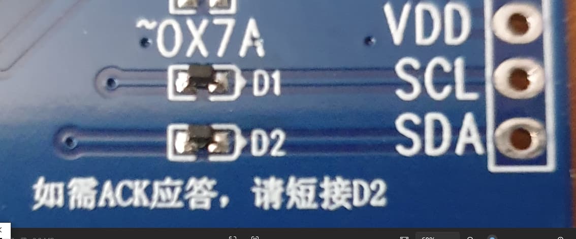
What I got was
If the answer is 0 watt, please short-circuit 02
So allowing for some errors as some things were in english (like ACK and D2)
My very poor translation become
“… If no ACK, please short-circuit D2…”
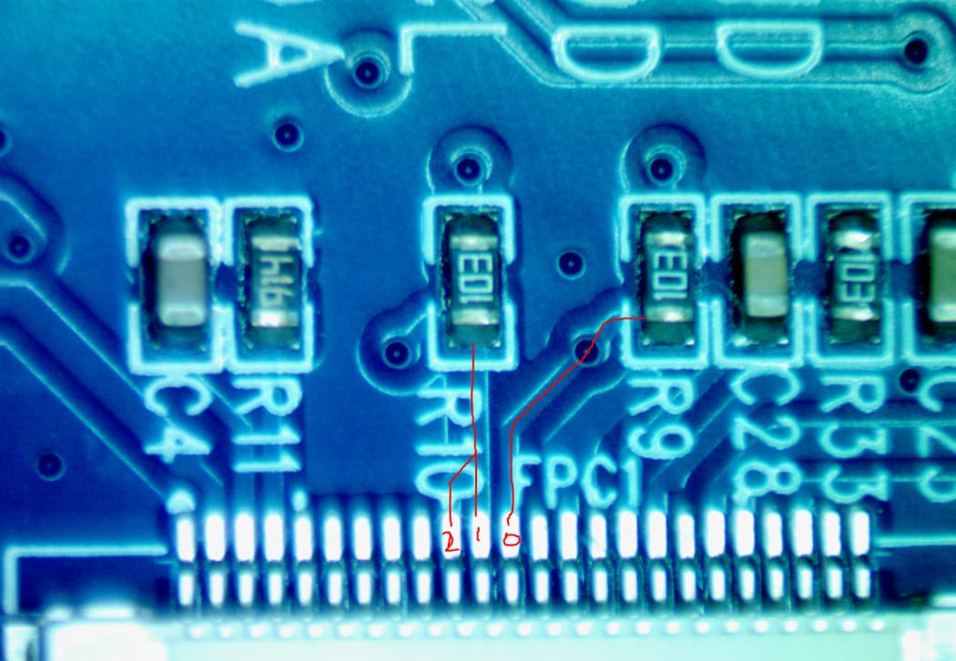
So being more then happy to break my own device ![]() I removed the diode on D2 and shorted the two pads.
I removed the diode on D2 and shorted the two pads.
After this was done, I can see the ACKs coming back when commands are addressed to 0xC3 (i.e. my logic analyzer shows good I2C comms).
So using the same setup as above, but back to a normal I2C bus and expecting ACKs, it seems to be working. i.e. using the SSD1306 driver with address 0x3C
I also tried other addresses and it did not work (as expected).
I hacked up an address scanner (but my not be doing this the best way) and the only address that gave a response was the 0x3C.
As such I am happy that the address is 0x3C, as when left shifted 1 bit we get 0x78 (ie the address on the board i saw in some photos) So I can only assume what is a very clear 0x7B on my board is an error.
1 Like
Just to value add the above.
From the datasheet for the SSD1309
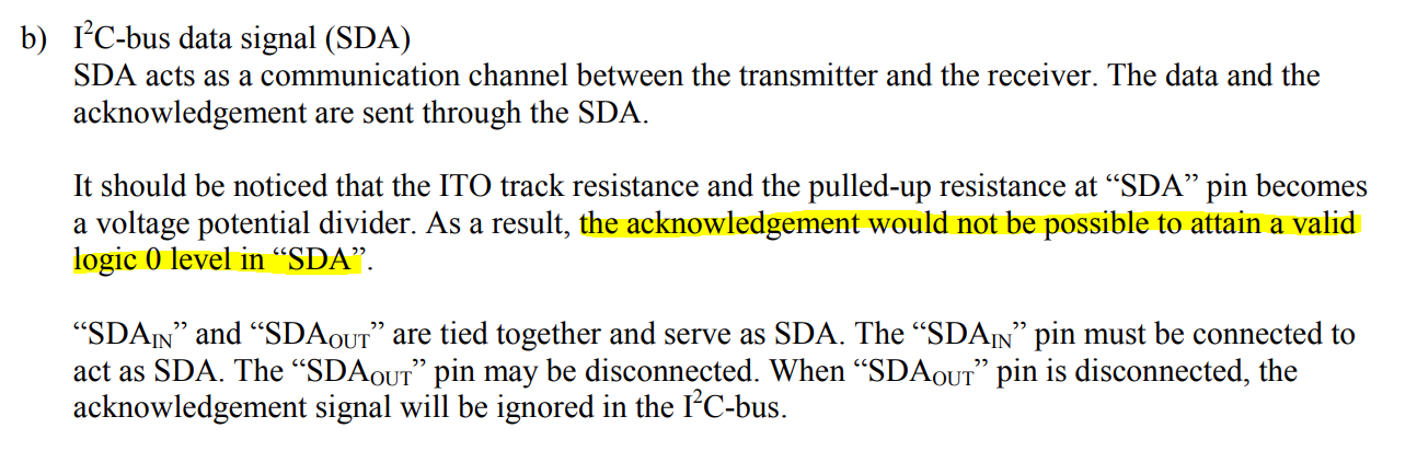
I take it that what it means is it wont actually get to 0V, but still low enough to trigger the 0 level logic.
I want to stress that this is the datasheet for the driver chip, not this board, as such its the use of the diodes that cause the issues (read on).
The logic voltage is 3.3V

D1 and D2 should be tied together to form the single SDA
D0 is the SCL.
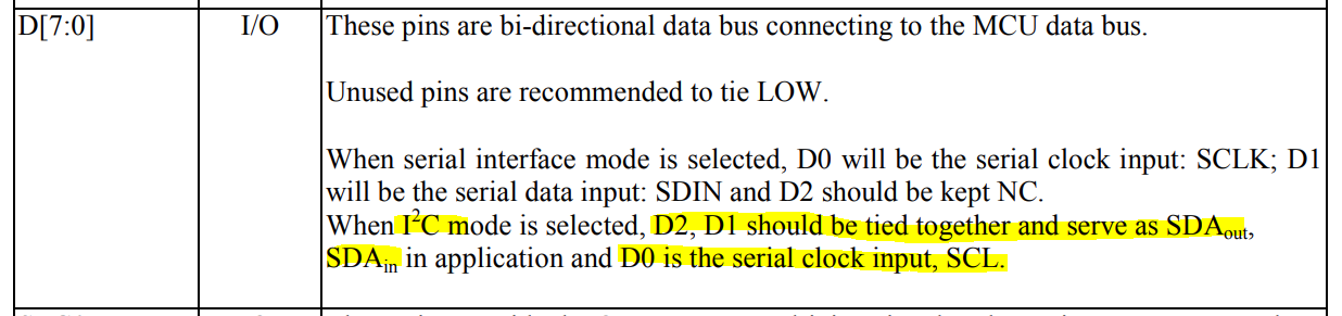
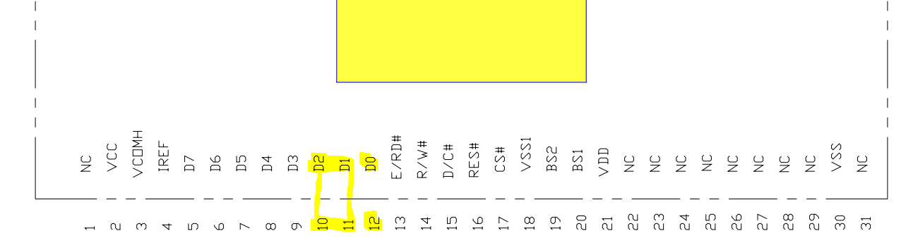
We can see D0 runs to a 10K pull up. D1 and D2 are joined and run to a 10K Pull up.
Both +V for the pull up is via a power regulator and not the VDD pin.
The D0 and D1/2 then go to the display side D1 (SCL) and D2 (SDA) diodes.
So in review of that part of the circuit we have a one way Logic Level Shifter protecting/ensuring the display components only see the 3.3V.
So when the I2C pins go low, the +V on the display driver is pulled down via the diodes, when the I2C pins go high, its no longer pulled down, rather pulled up by the 2 10K resistors (to the +V from the regulator)… i.e. not by the I2C bus as such.
So that all works if you don’t expect anything back from the display (i.e. don’t expect ACKs on the i2c bus). Leading to the display not really being i2c compliant.
i.e. When the driver chip pulls down the SDA line, it will go low, but due to the diode D2, it wont pull the I2C bus down, thus the master does not see any data, inc. ACKs.
As per my tests, if you disable the check for ACKs and just blindly send the data, it works. If you remove D2 Diode and replace with a short/link, this allows the bus to be pulled low when needed, thus working as a normal I2C device.
With D2 replaced with link/short a scan will find the device and the ack packets get back… just need to ensure you are only driving at 3.3V.
In theory the 10K pull up should also be removed, but its weak enough not to cause any issues in my testing.
In short, from my testing and review, i believe the display works fine and its the implementation of the driver voltage and diodes to protect/allow the device to run from a higher voltage, that is the issue. If you are running your VDD and I2C at 3.3V then the removal of D2 should be enough to make it work as expected.
The SDD1306 display driver code should work to drive the display
The I2C address is 0x3C (or 0x78 when left shifted) in its default state.
2 Likes
Just want to say: Michael, you’re a legend!
I’m basically doing my first electronics project, so I had no clue what was wrong. I was a bit wary of immediately desoldering it, so I made the worlds tiniest horseshoe out of wire and blue-tacked it onto D2.
For those of us mere mortals who are using MicroPython, I can confirm that once D2 is shorted:
- PerfecXX’s library for SSD1306 works
- rdagger’s library for SSD1309 also works
- I tried the second library while trying to figure out what was wrong
2 Likes
Hi @James286481,
Welcome to the forum!
That’s some top-tier resourcefulness with the horseshoe and blue tack, true maker spirit right there ![]()
Really glad to hear it’s all working now, and thanks for confirming those libraries play nicely once D2 is shorted. That’s super helpful info for others running MicroPython. Appreciate you jumping on the thread to share your experience, and props again to Michael for the solid detective work
Amazing work @Michael99645 …
My display worked right off on my Pico 2W… but, I’d really like to have two of these… however, unlike the little brother device, this one has no “ASW” address switch, so it looks to me like the 0x3C address is locked in. If I’;m right… that’s a pity. Perhaps rev 2 of the board could add an ASW?
Cheers, T.
Hey @Trevor277988 ,
You should be able to move the small resistor on the back of the board from the spot marked 0X78 (may look like 0X7B) to 0X7A to change the I2C address for this display, however, I tested this on a few displays, and this didn’t seem to change the address at all, which is a little annoying.
Your Pico 2W actually has two separate I2C channels, so as long as you only need to use two displays with the same address, you should be fine. The two channels use separate pins on the board marked as either I2C0 or I2C1.

We have this great video guide going through I2C on the Pico. you can see the code and how you would change it to use either I2C0 or I2C1 at around the 4 min 30 sec and onwards in the video.
Hope this helps!
1 Like
I’m quite familiar with the Pico and thw 2 I2C buses… but I need both OLEDs on the same bus for my app. - I2C1 will be running at a lower clockrate for my VL53L1X on a custom 1m cable.
I’m also aware of the code in the driver for changing address… but, if the board itself isnt configured for the other address… I’m stuck
Your test that did NOT change the address is a bit worrying…did you confirm with a scan that it was still using 0x3C?
Cheers, T.
Hi @Trevor277988 ,
Ahh I see. Unfortunately, yes.
I used a Pico 2W running code to scan the available I2C addresses of 3 of these displays, which all read as 0x3C before removing the resistor and moving it to the 0X7A spot on the board and running the test again. They all returned as 0x3C.
I then tried a control with no modification, another one with the resistor swapped over and a third with the resistor completely removed and had them all return an address of 0x3C. I tested these with some code to display a bit of text, and they all work when using this address, even after modification.
Bit of a weird outcome, so I would conclude that the ability to change the address was considered at some point in the development of this board, but didn’t make it to the final product, which is annoying. I have let our team know, so that we will update the product page to reflect this information.
If you need to run two of these displays on the same I2C channel for your project, you should be able to use an I2C multiplexer like this one: