ok, testing has been competed on the motor with no load on the platform and also with full load of the telescope. Please see poits below.
No significant difference in performance between load and no load. they performed almost identically.
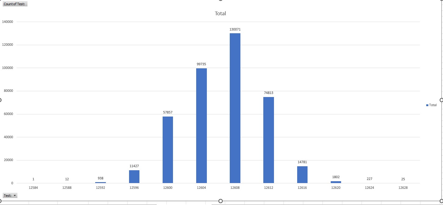
2.Interestingly medium step duration = 12608 μs where as the code is 12620 μs. Think it has to do with the 10 μs delay
 // Handle normal tracking steps
    // These lines result in 1 step:
    if (micros() >= next_Micros) {
      next_Micros += delay_Micros;
      digitalWrite(stepPin, HIGH);
      delayMicroseconds(10);
      digitalWrite(stepPin, LOW);
    }
from the medium step duration of 12608 μs the slowest steps where 12588 μs, 20 μs slower and there where only 12 of them.
from the medium step duration of 12608 μs the fastest steps where 12628 μs, 20 μs faster and only 25 of them
I wont go into any further analysis but i have provided a snapshot of a table for reference and if you would like to see the spreadsheet im also happy to post that.
Microseconds are hard to conceptulise but im guessing the deveiation of ± 20 μs are within acceptable tolerances and wouldn’t effect the tracking accuracy of my platform?
Could the above issue im having with powering the arduino from the 5v pin be a culprit for the motor innacuracies?
That will happen if the driver has a regulator for its own logic, supplied from the motor power. It will feed that supply to an attached controller. Some drivers will have a jumper to select the power source, others have a protection diode so it takes power from whichever source is higher. But the power source should not affect the MCU timing.
This test will not be affected by the load - it is purely to confirm that the Arduino is generating the step commands correctly. I think you have proved that, although it would be good to know exactly why you got those odd results at first, because that could indicate an intermittent problem. You could leave this monitoring in place when you make further changes, to be sure that it is continuing to operate correctly.
The variation is not due to the 10uS delay. That delay only happens when a step occurs, and a step only occurs when a tick has been detected. When that happens there is ~12620uS before the next one, so there is plenty of time for all the commands of the step pulse, including the delay, to occur. In fact, one of the changes you could make is to increase that delay to ensure it is well within the specs of the driver. The variation occurs because the time is being checked once per loop, and the loop takes a definite amount of time to complete. So sometimes the check occurs immediately after the time has expired, and sometimes it occurs several uS after the time has expired. The small variation and the randomness you have recorded would not be the cause of a perceptible slowing down and speeding up of the movement.
The next step is to see whether the microstepping is the problem. Each doubling of the microstepping almost doubles the torque available. I would suggest running the camera at 1/8 microstepping with double the 12620 uS delay. Or, 1/4 microstepping with quadruple the delay. Some adjustment of the delay might be required to maintain positioning, because the relationship involves the loop execution time, which doesn’t change with the microstepping, but the adjustment would be small. Then check for the speed consistency using the same technique by which you originally discovered it.
Unfortunately to test I need a cloudless night to actually image something then review all the images. So with our current weather in Sydney who knows when that will be
I think first test will be removing buck converter and running Arduino off a USB charger and motor off the 12v see if that improves anything. As mentioned with the timing issue there was multiple events where the delay was significantly over 12620, so hoping the USB power to Arduino helps. Would love to solve the timing issue so I can keep the buck converter and only need a single power supply but I think that’s a battle for another day.
In regards to lowering the microstepping I have done similar testing in the past and I just dug up my results. I take continuous 10 second exposures of a bright star and look for variations in its position and distortions from sudden movements. At 32 microsteps I had about 55% acceptable images and at 16 microsteps about 65 % of acceptable images. Not sure if this was conclusive or significant. Problem is that dropping down to 1/8 1/4 introduced significant vibrations and led to the motor skipping steps and not working properly.
It’s always been in the back of my mind to get a stepper with a 100:1 gear and running it at 1/4 or 1/8 microstep and see if that makes a difference.
Unless I am reading your schematic incorrectly then you are already running the motor off 12v. I would not expect that removing the buck converter will help - if anything it might hurt, because at the moment it is acting as a kind of buffer between the 12v supply, which might be subject to transients when the motor is driven, and the Arduino. But it’s a simple change that can be easily tested.
The vibration will be greater at 1/8 or 1/4 microstepping, but missing steps doesn’t sound right. The point of dropping the microstepping to those values is that you get more torque, and the chance of missed steps should be reduced. The only reason this might not happen is that the torque required for the greater movement distance increases more than the torque available increases. If that’s happening a bigger motor or more gearing is the only answer (assuming reducing the inertia is not an option).
If you did that you wouldn’t run at 1/4 or 1/8 microstepping - you would leave the microstepping at 1/16, and increase the number of steps per timer tick. The whole purpose of microstepping is to smooth the motion - it is not intended to increase the resolution of the stepper. Multiple steps per timer tick gives smoother motion without the problem of insufficient torque with individual 1/16 microstepping.
12v power supply gets split into two, one end goes directly to driver and other goes into buck converter to drop down to 5 volts and then power Arduino through 5v pin. I was thinking of removing the buck converter and no longer powering through 5v pin, just power it with USB. Are you suggesting I should leave the buck converter for 5v power to pin and also power via USB to remove the timing error?
Ah right, I thought by upping the gearing by 4x i could reduce the microstepping by 4x to achieve similar results. So if after my next level of testing i’m still finding errors which may fixed by lowering microsteps what are my options regarding motors?
That would work, but you wouldn’t get the smoothing effect that 1/16 microstepping provides, and your previous experience with 1/4 microstepping indicates that the smoothing is important.
A bigger one. For instance, I have a spare one you could have that I think is much larger than anything Core stocks, and has the advantage of a wire spindle drive, which gives you an easy way to create better gearing. And it’s local! Stepping motor 86SH-62B2B | eBay
is spot on. If the torque reduction due to microstepping proves to be a problem then I think the only way to get smooth motion would be a brushed motor. The speed could be trimmed using PWM but once again due to the vast magnification of any errors the PWM might have to have a better resolution than the 255 steps on offer with built in systems.
Be aware that the gearbox ratios quote on many of the gears motors on offer are usually not accurate. that is 100:1 will not be EXACTLY 100:1. This may not be a problem in most applications but in your case a bit of speed trimming would be desirable to get the required speed. PWM control would have another advantage when moving rapidly between 2 points as it can fairly easily be speed up to suit the requirement then reduced to operating speed. This inaccuracy of the gear box ratios would make an encoder on the motor shaft meaningless but would be better implemented on the actual telescope mount somehow.
Cheers Bob
I will report back once I’ve tested the platform with the USB power that seems to fix the timing issue. Unfortunately, the forecast suggest it may be a couple of weeks until I can get under a clear night sky.
Thanks Jeff. If im having no luck ill be sure to get in touch
I assume you’re trying to run a constant speed that gives 15°/hr gearbox output .
Using delayus isn’t a reliable or recommend method. The Arduino write digital command is very slow in microcontroller terms. I can well imagine these 2 things being the root cause of your variations.
Why not use a library like accelstepper ?
I don’t know why. Im not well versed with the language and managed to scrape out a version for my platform quite a while ago and it was edited by some one in the astronomy community to increase performance and avoid cumulative errors.
Dont even knwo where to start to try convert this to accelstepper but will have a look.
OP is single stepping, so AccelStepper will not provide any advantage, and in any case the library uses digitalWrite to provide the pulse the driver needs, so in fact it adds more instructions into the loop without achieving anything. But the time taken to do the step is not an issue because OP has 12620 uS between steps. If the gearing is changed so that there are multiple steps per timer tick accelstepper might be worthwhile to smooth the step, however it is likely that it will not be needed. For instance, the vibration noted could be addressed by moving the shutter trigger to a different point of the timing cycle. If necessary, accuracy of timing will be improved by using an interrupt instead of polling.
But at the moment the issue is the speeding up and slowing down, not the 4-12uS variation in timing. The current task is to determine whether or not this due to the motor skipping microsteps, as seems likely.
It’s an example - a simple way to show OP the item. Also chosen because it demonstrates the ridiculous expectations of people putting items on EBay that are otherwise available for the cost of local delivery.
Just finishing up a very frustrating night with the scope. Unfortunately no improvement powering the Arduino via USB as compared to the buck converter 5v.
Jeff was hoping to direct message you regarding that stepper you have for some info and if you want to sell but can’t figure out how to send a direct message.
The facility for PM seems to have disappeared. I have disabled the junk filtering for the moment, so go here and submit some feedback with your email. That will get to me. The stepper is available for the cost of collection, which might be nothing if you live in the right part of Sydney. I have a range of recovered units which are suitable for hobbyists. This is the largest, but there are others that might also be suitable. They all work, but getting specs for them is difficult so experimenting might be required. You have to promise to send a photo of the completed project
Yes definitely! I have some images to share now but each come with the pain of rummaging through hours of data to remove all the problem frames from the tracking issues I’m having. I’ll be sure to post a stress-free image once I get this platform working as well as possible.
P.s My telescope is dobsonian and thus isn’t an imaging telescope hence the need for DIY projects to do some very basic imaging but I wouldnt have it any other way
Really interesting topic, using an Uno kind of like a logic analyser is a great tool!
There might be some odd fluctuations in the voltage causing the clock to vary speeds. If the 12V line doesn’t see any over-voltage you could try hooking that up directly to the Vin (7-12V input), then you’ll get all of the filtering that comes with the inbuilt power chain.
Unfortunately without a scope it will be hard to see what is happening. Though the USB power bank should supply clean-enough power for the micro.
And a super interesting conversation just surrounding the rest of the project, we’re keen to see how it goes!
Ahhh, Thanks Liam, very interesting. I will try this. Do you think i should go 12v straigh into vin or maybe 12v into the buck converter to drop it to say 9v then into vin for mroe safety? i’ve also got a 100Uf capacitor which im thinking of including to help with any electrical noise.
P.s are there different levels of standards with power supplies? for example im using a power supply that came with a computer modem.
In terms of inputing via 12V, I would add a Schottky diode to make sure there isn’t any reverse voltage (side with the band pointing towards the Vin pin).
Stepping the voltage down again might introduce more noise if a switching supply is used, to keep variables down it might be good to leave it out for testing.
I’m not too sure off the top of my head! I’d say your supply will work fine to power your project, just be sure to stay well within the quoted current output
Usually, any specs are listed in the datasheet this would include, switching speed, noise, and regulation just to name a few, I’ve had good experience with different types of Meanwell supplies, here’s an example datasheet: https://www.farnell.com/datasheets/2547969.pdf