I’ve been trying to get my HAT to place a Raspberry Pi 4 on The Things Network. I’ve tried various Raspbian releases (Bullseye → Trixie) with limited success. On later releases of Raspbian I am using some updated scripts to deal with the deprecated ‘echo > /system/class/gpio’ pattern that instead use the gpioset command.
At this point I’ve tried most things found on this forum and the wider internet support community. Just wondering if anyone has a working setup and could provide a set of commands with output to show how the working hardware should respond.
I.e. run this command → get this output.
I’ve run gpioinfo with/without the HAT - before and after running the reset script but the output looks the same.
Only the “sudo i2cdetect -y 1” command gives different chip output with the HAT installed on the PI:
This is a bit out of my area, so hopefully someone else can jump in with some helpful information!
The output you are getting from i2cdetect tells us that, at least, the HAT is being detected by the Pi at the expected I2C address (0x39), so your physical connection is likely correct.
I have captured the gpioinfo status before and after the reset script runs.
Here is the status after a cold boot:
lora@lorapihub:~ $ gpioinfo
gpiochip0 - 58 lines:
line   0:	"ID_SDA"        	input

line   1:	"ID_SCL"        	input

line   2:	"GPIO2"         	input

line   3:	"GPIO3"         	input

line   4:	"GPIO4"         	input

line   5:	"GPIO5"         	input

line   6:	"GPIO6"         	input

line   7:	"GPIO7"         	output active-low consumer="spi0 CS1"

line   8:	"GPIO8"         	output active-low consumer="spi0 CS0"

line   9:	"GPIO9"         	input

line  10:	"GPIO10"        	input

line  11:	"GPIO11"        	input

line  12:	"GPIO12"        	input

line  13:	"GPIO13"        	input

line  14:	"GPIO14"        	input

line  15:	"GPIO15"        	input

line  16:	"GPIO16"        	input

line  17:	"GPIO17"        	input

line  18:	"GPIO18"        	input

line  19:	"GPIO19"        	input

line  20:	"GPIO20"        	input

line  21:	"GPIO21"        	input

line  22:	"GPIO22"        	input

line  23:	"GPIO23"        	input

line  24:	"GPIO24"        	input

line  25:	"GPIO25"        	input

line  26:	"GPIO26"        	input

line  27:	"GPIO27"        	input

line  28:	"RGMII_MDIO"    	input

line  29:	"RGMIO_MDC"     	input

line  30:	"CTS0"          	input

line  31:	"RTS0"          	input

line  32:	"TXD0"          	input

line  33:	"RXD0"          	input

line  34:	"SD1_CLK"       	input

line  35:	"SD1_CMD"       	input

line  36:	"SD1_DATA0"     	input

line  37:	"SD1_DATA1"     	input

line  38:	"SD1_DATA2"     	input

line  39:	"SD1_DATA3"     	input

line  40:	"PWM0_MISO"     	input

line  41:	"PWM1_MOSI"     	input

line  42:	"STATUS_LED_G_CLK"	output consumer="ACT"

line  43:	"SPIFLASH_CE_N" 	input

line  44:	"SDA0"          	input

line  45:	"SCL0"          	input

line  46:	"RGMII_RXCLK"   	input

line  47:	"RGMII_RXCTL"   	input

line  48:	"RGMII_RXD0"    	input

line  49:	"RGMII_RXD1"    	input

line  50:	"RGMII_RXD2"    	input

line  51:	"RGMII_RXD3"    	input

line  52:	"RGMII_TXCLK"   	input

line  53:	"RGMII_TXCTL"   	input

line  54:	"RGMII_TXD0"    	input

line  55:	"RGMII_TXD1"    	input

line  56:	"RGMII_TXD2"    	input

line  57:	"RGMII_TXD3"    	input
Here is the status after running the reset script:
lora@lorapihub:~/src/sx1302_hal/tools $ gpioinfo
gpiochip0 - 58 lines:
line   0:	"ID_SDA"        	input

line   1:	"ID_SCL"        	input

line   2:	"GPIO2"         	input

line   3:	"GPIO3"         	input

line   4:	"GPIO4"         	input

line   5:	"GPIO5"         	input

line   6:	"GPIO6"         	input

line   7:	"GPIO7"         	output active-low consumer="spi0 CS1"

line   8:	"GPIO8"         	output active-low consumer="spi0 CS0"

line   9:	"GPIO9"         	input

line  10:	"GPIO10"        	input

line  11:	"GPIO11"        	input

line  12:	"GPIO12"        	input

line  13:	"GPIO13"        	output consumer="gpioset"

line  14:	"GPIO14"        	input

line  15:	"GPIO15"        	input

line  16:	"GPIO16"        	input

line  17:	"GPIO17"        	input

line  18:	"GPIO18"        	output consumer="gpioset"

line  19:	"GPIO19"        	input

line  20:	"GPIO20"        	input

line  21:	"GPIO21"        	input

line  22:	"GPIO22"        	output consumer="gpioset"

line  23:	"GPIO23"        	output consumer="gpioset"

line  24:	"GPIO24"        	input

line  25:	"GPIO25"        	input

line  26:	"GPIO26"        	input

line  27:	"GPIO27"        	input

line  28:	"RGMII_MDIO"    	input

line  29:	"RGMIO_MDC"     	input

line  30:	"CTS0"          	input

line  31:	"RTS0"          	input

line  32:	"TXD0"          	input

line  33:	"RXD0"          	input

line  34:	"SD1_CLK"       	input

line  35:	"SD1_CMD"       	input

line  36:	"SD1_DATA0"     	input

line  37:	"SD1_DATA1"     	input

line  38:	"SD1_DATA2"     	input

line  39:	"SD1_DATA3"     	input

line  40:	"PWM0_MISO"     	input

line  41:	"PWM1_MOSI"     	input

line  42:	"STATUS_LED_G_CLK"	output consumer="ACT"

line  43:	"SPIFLASH_CE_N" 	input

line  44:	"SDA0"          	input

line  45:	"SCL0"          	input

line  46:	"RGMII_RXCLK"   	input

line  47:	"RGMII_RXCTL"   	input

line  48:	"RGMII_RXD0"    	input

line  49:	"RGMII_RXD1"    	input

line  50:	"RGMII_RXD2"    	input

line  51:	"RGMII_RXD3"    	input

line  52:	"RGMII_TXCLK"   	input

line  53:	"RGMII_TXCTL"   	input

line  54:	"RGMII_TXD0"    	input

line  55:	"RGMII_TXD1"    	input

line  56:	"RGMII_TXD2"    	input

line  57:	"RGMII_TXD3"    	input
We are recreating your setup on our end to help troubleshoot this, and ran into the same issue it sounds like you experienced, where the library tries to use the olde,r outdated GPIO method.
It sounds like you got past that hurdle already. Would you be able to share a link or some instructions for how you overcame this so that we can more accurately replicate your setup?
Amongst the changes it updates the original scripts to make them more compatible with Trixie. This repo uses the new ‘gpioset’ commands. The old https://github.com/Lora-net/sx1302_hal script uses a deprecated ‘echo > /system/class/gpio’ pattern.
Please let me know if you need any more info - I’m pretty sure that’s all I did but did so many changes its possible I have hacked something else to get further.
Thanks for sharing that link. I was able to get this working on a test setup using a Pi 4, so that library hopefully isn’t the problem.
Would you be able to try again from a fresh SD install of the latest version of the Pi OS, make sure I2C and SPI are enabled through the raspi-config interface, and that github library?
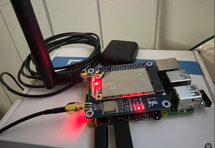
If that still doesn’t work for you, then some photos of your physical setup would be helpful as its likely a hardware problem after that.
Hi Samuel, I did a fresh build and enabled the I2C and SPI interfaces. I tried reseating the HAT a few times - with and without the supplied riser and it made no difference to my previous results. I also tried without the stand-offs to see if I could get a better connection (as per the photo).
Based on the difference results you and Sam are getting, I think this would be worthwhile escalating to Tech Support and exploring as an RMA.
Could you please email us at support@coreelectronics.com.au linking to this thread with a photo of the front and back of the Pi and HAT and we can move onto getting this resolved as quickly as possible.