Part of that was creating a control unit and my colleague happened to have a Cambridge decade bridge which was at the end of it’s life. We took it apart and all the components were shot. I salvaged what I could.
My friend wanted this to be a serial control unit that could interface with his computer for music so I digitized everything with some rotary encoders.
Look maybe this is a bit like if my kid came up to me and said my CD collection looked shiny but I have absolutely fallen in love with these old components.
They’re giant potentiometers !
Unfortunately the resistors are all shot and most of them don’t work. The circuit has been broken in all of them. It’s hard to assess continuity with the resistors everywhere.
Despite it being daunting, I want to give these things a second chance. I’m fully prepared for this to be a long process and I’m coming at it humbly.
Whoever had it last has definitely been hacking at this before me. Lot’s of missing pieces and modern cabling where it shouldn’t be.
There are a lot of people on these forums with heaps of experience. If anyone has any idea what these are called, any schematics, or how to approach it I’m all ears.
For a short while I owned a Cambridge Instruments Wheatstone bridge similar to this - they are works of art! Those chunky copper leaf/brush wipers are unreal aren’t they
I’m afraid I don’t have much considered advice to provide, just an agreement that this old test equipment has a really satisfying build quality and history to it and your plan to attempt restoration is admirable
If the contacts are all good and it’s just the precision wound resistors that are in need of replacement perhaps there’s some exotic, high-precision single value resistors you can substitute in?
Else… you can have a go at winding them again yourself. After all, the accuracy is obtained by hand tuning the wire length until the correct resistance is achieved. A great opportunity to set up a Kelvin measurement to ensure accuracy as you go.
There are plenty of wire-winding projects and writeups scattered over the internet.
Best of luck to ya Pix. Looking forward to seeing how you go and helping with anything if we can
If I had to guess, I’d hazard that the simplest way to make a very accurate resistor with pre-moon-landing technology is to wind it out of copper and tune the length of the winding to achieve the desired resistance. Or perhaps the resistance/metre is well-known enough that they just wind the resistor with a known length of copper wire and can be sure that the resistance is within the required tolerance.
The modern equivalent of this practice is Laser trimming - where resistive material is ablated away with a laser to precisely tune the overall resistance.
Magnet wire. Gotcha.
Thanks Michael. That’ll get me started. It was unimaginable to me that I would one day be seriously considering handwinding my own resistor.
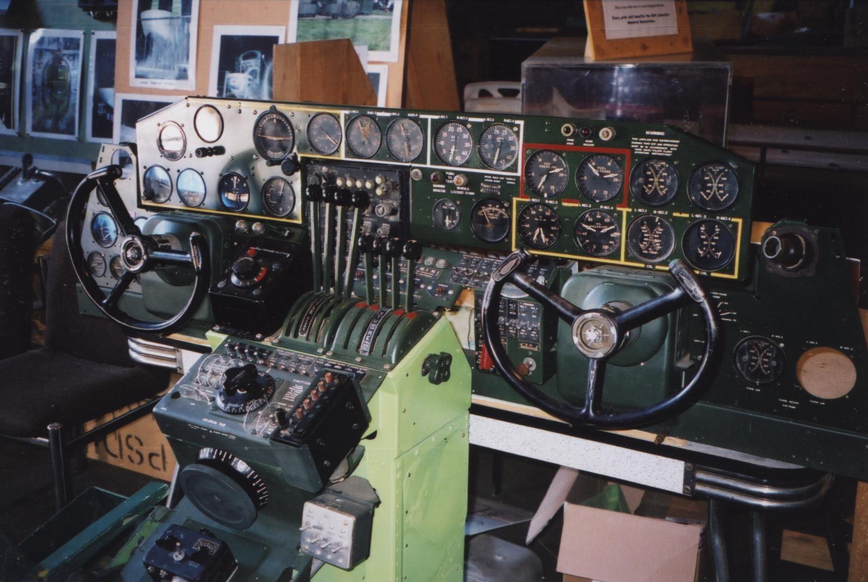
My dad was trained as an Armature Winder by the Air Force in the Second World War, his job was to repair the electric motors on the Liberators and other bomber aircraft. And any other electronic parts.
Yes he did built a lot of parts by hand, tuning coils inductors and such. The amateur radio transceivers he built in the 60’s while I was watching used purchased resistors and capacitors. But he was quite capable of making these if he needed. Can’t pop into the local electronics shop in the middle of a battlefield.
I think when that instrument was built and when they wanted a low resistance contact they really went out of their way to make sure of it.
At the present time there is available a series of 0.1% tolerance resistors from various suppliers if rewinding the originals seems too daunting. These would do the job if what you want to do is restore the instrument to operation. Would not do of course if you want to do a restoration back to original. I would not think a tolerance of any where near 0.1% would have been available in a ready made form in those days hence the winding of the components.
You would have to check an original resistor to see how it is constructed. I think they would have to be BIFILAR wound . If not there would have been an enormous amount of inductance involved which would have made this instrument useless for anything but DC. I have never really used one (particularly of this age) so can’t comment too much. I imagine one of the main uses would be to experiment with different DC biasing levels for valve, transistor etc circuits. or to provide a reference resistance for some other instrument (Wheatstone Bridge etc).
Cheers Bob