I have tested it and it triggers just like the button.
Question one is:
How could I add a sort of delay to prevent accidental triggering?
It will already only operate once the presence loop is activated, however people also use pass cards and may accidentally trigger the sensor, which stops pass card use.
I was thinking they need to hover intentionally for 1-2 seconds for trigger to avoid this.
Question two is:
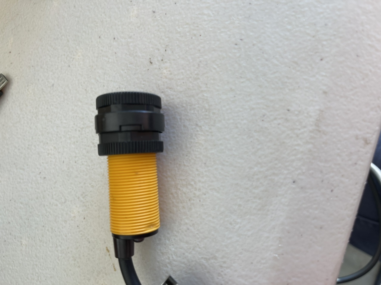
Is there some sort of sensor I could use for outdoor environments?
It can be power by either 5,12 or 24v(less preferred) and only needs a trigger on
If you meant just a delay to stop that one from being used again for a few seconds, something like a 555-timer circuit would be a good option. I just found this example online that looks like it’d suit what you’re after.
What I need is to prevent it from being instantly triggered.
At the moment, as soon as the sensor is triggered it sends an immediate pulse to the I/O board it is connected to.
What I would like is to be able to delay the pulse from initiating for ~2 seconds.
Retriggering is not an issue in this case.
Ideally a low profile and cost solution.
If both don’t exist together, then low profile is preferred.
Another 555-timer circuit like this would be super suitable then! That’s probably the lowest cost/low profile solution I can suggest as it just requires the 555-timer IC, some resistors, and a capacitor! Just note you will need to change the passive components values to suit the 2 second delay you were after.
Someone else might be able to chime in with a better option though.
Hi all.
555 timer??? there have been volumes written about this seemingly forever useful little beastie. I have got a couple. IC Timer Cookbook by Walter G Jung and one of the Engineer’s Mini Notebook series published by Radio Shack.
It has been around for it seems like centuries and I think is destined to be around for a long time yet. Should be on everyone’s reading list. Very simple and possibly one of the most useful ICs commonly available. Comes in a couple of flavours these days. Dual and Cmos versions.
Cheers Bob
I copied this exact method and got an led with a 1 second delay on 5v.
Thanks Owen.
It’s currently hooked into a breadboard for testing.
I will test out with the actual sensor tomorrow.
Granted it works as intended, how would you package this in a working environment?
I could simply cover the breadboard in some way and be done with it for the test unit. Not sure if ideal in a live environment.
While my bare electronics knowledge is still lacking until my reading about it makes it off the backburner, my understanding is that all you’d need is a NOT gate on the input of your 555 circuit?
That circuit would be at the the output, not input. It seems that the sensor is currently operating as a switch to ground. The 3.7v at the switch when it’s open would be a pullup resistor. Currently the 555 is configured to be a current source (ie, high voltage) when triggered, so it turns the LED on by creating a current to ground through the LED and its resistor. This has to change to being a current sink, pulling the signal to ground, like the existing sensor is doing. The inverter you have linked to will do this: when the 555 output goes high the transistor turns on, passing current to ground like a switch.
Thanks for the correction, I’ve only used 555s in astable mode, and even then my knowledge was just enough to get it going, so I’m glad we’ve got a second opinion on this one!
The last step is adding an LED to present the customer.
The ideal solution would be a buy colour LED (green/red) and have it start red and when the pulse is triggered it turns to green. We will display a message and have signage to reflect what the customer needs to do.
I’m not sure how I will invert the polarity to do this as I would like to only have one LED.
Is this possible within the current setup with minimal additions?
I managed to figure it out.
The cathode of the bicolour LED connected to ground and the anode to the NO contact.
What an annoying but satisfying journey.
Hi Anthony
I have used bi colour (R,G) in the past. The particular type showed RED one polarity and Gr with opposite polarity. I used 2 OP amps to switch polarity. The LED connected with its current limiting resistor between the outputs. The operating pulse applied to both OP amps, one inverting the other non inverting.
I have not tried but you could do the same with 2 Ardinuo outputs. Connect the LED/resistor combination BETWEEN the outputs instead of to ground and alternate the 2 outputs, one high and the other low.
Cheers Bob
Add on to my last post.
Have just got around to trying a bi colour LED between 2 Arduino outputs. Works fine, I am sitting here watching it blink away red, green, red and so on.
A bit of useless info I know but someone may be interested.
Cheers Bob