ULN2003 is not working when connected to external power and Raspberry Pi

The picture above is the circuit I’m trying to get to work. All my existing Raspberry Pi power pins are taken up by a camera multiplexer which powers 4 RPi cameras). So I am left with no power pins to connect the stepper motor to, and hence wanting to use external power of 5V-12V. But the problem is the motor and driver only works when I connect them directly to the 5V on RPi (when the camera multiplexer is not present) but it doesn’t work with external power.

Here is my current setup:

  • Motor: 28BYJ-48 stepper

Driver: ULN2003 driver board

Controller: Raspberry Pi 5

Power: External 5V DC adapter (verified working with LED circuit)

GPIOs used: GPIO 12, 16, 20, 21 (BCM mode)

GNDs connected: Raspberry Pi GND and external power supply GND are connected together

Driver board is powered via external 5V and GND (not from Pi)

Things I’ve tried so far:

  • Verified my external 5V adapter works using a simple LED+resistor test.

Ensured all GNDs are tied together (Pi GND, ULN2003 GND, power adapter GND).

Swapped to a second ULN2003 board and a second stepper motor — same result.

Removed the breadboard and directly soldered ground wires to eliminate poor contact.

Ran a GPIO test script to confirm GPIO 12, 16, 20, 21 go HIGH — all passed (LED blinks correctly).

Double-checked GPIO pin numbering (I’m using GPIO.setmode(GPIO.BCM)).

Tried running stepper motor control code as sudo.

I am following the exact circuit shown in the image. I don’t know what I’m doing wrong. Could someone please help me with this? I’d greatly appreciate it. Please feel free to ask if more details are needed.

1 Like

Hey @Hasitha294850, welcome to the forums!

I can’t see anything immediately wrong with this circuit. I would double-check the current rating on your external 5V adapter. If it works for an LED but not for this motor, there is a chance that it isn’t able to provide enough power?

Can you see a current rating anywhere on your External 5V DC adapter?

Hi Samuel, thank you for your response.

I can see the current rating as 3A for 5V - 12V on my external adapter.

I have a new problem now after trying another method. I changed up some GPIO pins and I connected the power directly from my raspberry pi 5V pin. The LED lights on the ULN2003 driver are lighting up (very faintly) according to my logic in the code but the motor doesn’t run. How can I supply more current to the circuit?

Thanks in advance!

Hi Hasitha294850

There might be a bit of a terminology problem here.
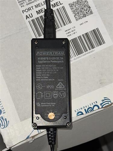
Is that 3A the rating for the barrel jack adaptor with the green terminal block or is it for the actual power supply plug in unit that plugs into the mains power socket.

The “5V - 12V” is suspect. I would not expect to see that on a power supply. I would only expect to see 1voltage as an output. Makes me think it is the rating on the barrel jack adaptor.

I think it would be the rating of the actual power supply that Samuel wants.
Cheers Bob

1 Like

I see. I am not great with electronics so I might’ve read that wrong. Here is an image of the adaptor that provides more information.

When I power the driver through the Pi only and in that case, even if I think that the camera multiplexer hat is the problem and remove the hat entirely, the same problem exists. The LED lights blink but the motor doesn’t run. I’ve run into the same problem a week ago so I switched the driver and motor for new ones and then they worked fine. However, when I connected the hat it gives me this problem even if I disconnect it later.
Hope I am making sense.

1 Like

Have you been able to get the setup working without the hat, after it failed? If not, that suggests that using both the hat and the external power has damaged something. If you can power everything down, remove the hat and then set up the motor driver with external power and get it going again, then that indicates that the hat is creating some sort of interference through the GPIO pins. Have you confirmed that the hat does not use any of the pins you have selected for the motor driver? A dim glow from the driver LEDs could be caused by the MCU trying to drive the GPIO pins at the same time as the hat.

1 Like

The driver and motor don’t work with external power regardless of if the hat is connected or not. The dim glow now exists even after I took the hat off (this is the case where I am powering it with the 5V pin from the Pi). I have tried it with new driver and motor now and it seems to function okay (again, without the hat). The old ones however, still give out the dim light.
You might be right that the hat is probably creating some sort of interference or even damaging the GPIO pins. I just need a workaround for this as I really need to run both the motor and the cameras on the same RPi board.

I am trying to build a turntable that is powered by the stepper motor. The 4 cameras that are connected are supposed to take photos of the subject as the table turns step by step. And I need to be able to control all of this from the same RPi board.

1 Like

If there is some sort of interference between the motor driver and the hat then you need to investigate the hat in detail. For instance, it is possible it has some functionality that you are not using but is nonetheless active, and you could turn it off. Or perhaps there are other GPIO that will not create the interference.

Without knowing the details of the hat and how you are using it to control four cameras it is just guesswork as to what might be going on, but it seems clear that you should not be doing more testing with both installed until you have much more information. The supplier’s website might have the details you need for the hat, or searching using the brand name and model number might reveal some detail pages for the module.

1 Like

This is the hat I am using if that helps -

And here is the setup guide for it:

1 Like

Hi Hasitha
There is one very important bit you MUST check.

Is the positive voltage available at the correct barrel jack point. In other words is the voltage from the external supply the correct polarity.

I note that as far as I can see there is nothing marked on the power supply to indicate whether it is positive or negative voltage on the centre pin. Some of these supplies have the negative on the centre pin and if this is the case you would certainly get the results you are experiencing.

I do notice that + and - is marked for the green terminal block but that will be wrong if the centre pin is negative.
Cheers Bob

1 Like

Hi Hasitha
Add on to above
Just looked up that power supply. It seems it comes with an assortment of barrel sizes which ARE reversible. That is you can have + or - on the centre pin.

That seems that it is ESSENTIAL you check polarity. It is possible you did this before connection. If so please confirm to eliminate this line of thinking. Double check anyway and please report finding so helpers are not going in circles.
Cheers Bob

1 Like

Hi Bob,

I assumed that the polarity was correct as the pin converter (if that is what it is called) had + and - symbols on it and I only connected the wires according to that. Here is a picture for reference. Please let me know if this is still a concern.

1 Like

Hi Hasitha

Yes this is very much a concern. The bit with the barrel on it has 2 pins to connect to the main lead rom the supply. This is so you can select any size barrel you want and can be connected both ways ie; reversed. If this has happened the + and - on the little adaptor will be wrong.

This is what I asked you to check above. The polarity has to be correct. A multimeter will tell you
Cheers Bob

1 Like

Use a multimeter to check if the external 5V is present at the VCC input pin of the ULN2003 board when connected.

1 Like

Thank you for your help everyone. It was a polarity issue after all. I fixed it now and it works fine!

Hasitha