Hi Guys I need help identifying this electronic part I think it’s a resister but there are no identifying rings around it any help would be appreciated


1 Like
Hi Ant
Does it look like it was all in one piece and has ruptured or is in fact 2 separate devices.
If we had some idea of where it came from it would help.
Cheers Bob
1 Like
Hi Bob,
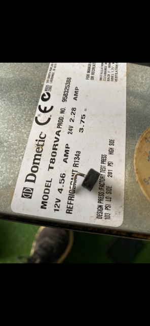
It was one peice and it came off a board for a 12v fridge
Thank you
A photo of the board showing the position it was removed from would be helpful. Also the make and model of the 'fridge in case there is a schematic available.
What was the failure mode? Was there an explosion or did the 'fridge just stop working and that’s what you found?
1 Like
Ok to easy ive attachex pics of everything.
The part in question started smoking when i swit Jed on the 12v supply and the part then broke into two peices I can’t see anything to identify it on the board either u fortunately.
Really appreciate your help


The best I can come up with is a diode, but it should have a visible ring marking one end, and would likely have a code number printed on it. There is an example here:
monitor display too big (electronicrepairguide.com)
This is an example of a component that has something to do with inrush protection, which looks very likely from the position on the PCB, but I can’t make sense of the description and in any case it doesn’t have any identification.
Szlifierka Kątowa Einhell - Identyfikacja Układu IC (elektroda.pl)
There is a link on that page which might have a little more detail.
So most likely a diode with all markings eroded by time and heat. It might be identifiable by physical dimensions.
I note that the manufacturer has a really helpful spare parts page - get the model number and call us and we’ll sell you the part!
1 Like
Probably limited to board replacement level.
But could still be economical.
Cheers Bob
Ok thanks Bob what would be the best number to call ?
2 Likes
Great work narrowing that down and finding somewhere to source a replacement!
Hi Jeff,
I’ve actually already contacted red Dometic and they said they wouldn’t have spare parts for it ? Screen shot attached

I thought that might happen. Actually, my comment was sarcastic, but I am aware that sarcasm doesn’t always come across well in the forums!
I you want to persist with this then the next step is to draw out the schematic in the vicinity of the failed item, including any markings that might still be there, and I’m sure someone would have a go at analyzing whatever is available with a view to confirming the component and suggesting a replacement.
Here’s a trick for doing a schematic from a PCB, which I only recently came across. Take a good square-on photo of each side, reverse the track side, and print them. Then, when you lay the printouts alongside each other the components on the top will match the tracks on the back so you can see exactly which through-hole applies to which component. The size of the printout makes it easy to add notes or whatever.
4 Likes
Hi Jeff
Good idea. If you have a printer with a scanner (most printers scan these days) sometimes scanning is successful. If it is important then you can get prints real size.
It is handy sometimes to print on transparencies then they can be overlaid
Cheers Bob
1 Like
A flatbed scanner works, but it has one problem: because it is designed to scan a flat surface there is only one light source and it is offset from the sensors. This creates a shadow in one direction which can make some features hard to identify. I have used a clear circular container with a hole cut in the bottom and a bright white LED strip wrapped several times around the outside. It is placed over the item, the camera sits over the hole for correct alignment, the container wall provides diffusion and the circular lighting gives a shadow-free image. Commercial units to the same design are available.
2 Likes
Hi Jeff
Very true. To be honest I have only done this a couple of times, it is not the sort of thing you have to do every day and I have managed to scrub around that problem.
The photo method is good but a half way decent camera is a great help. I am not a big fan of phone cameras but I agree that they are getting better.
I like that idea of a circular container but do you have a problem with the camera being a fixed distance from the subject. I imagine if the camera has a zoom function you would be able to frame up the subject OK. Must do some experimenting if I ever get time.
Interesting.
Cheers Bob
That’s a whole lot of electronics for a fridge. Peltier, maybe?
That idea of taking photos of each side of the PCB is great. If you can use Photoshop or similar, no need for a printer. And no need to get the perspective exactly right when you can just use a perspective correction tool.
Hi Kimmo
This fridge is apparently 12V so I assume it is in a caravan or similar. Some of these can be quite complex insofar they will operate 12VDC, 240vAC or LPG (Gas). And expensive.
Cheers Bob


