This is a placeholder topic for “VNH5019 Motor Driver Breakout” comments.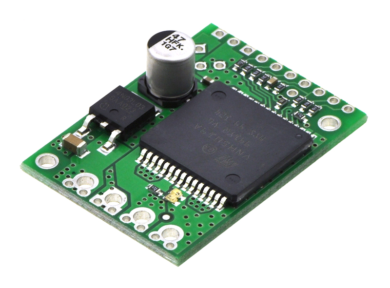
This carrier board for ST’s VNH5019 motor driver IC operates from 5.5 to 24 V and can deliver a continuous 12 A (30 A peak). It works with 2.5 to 5 V logic levels, supports ultrasonic (up to 20 kHz) PWM, and features current sense feedback (an analog voltage proportional to the motor current). Along with built-in protection against reverse-voltage, over-voltage, under-voltage, over-temperature, and over-current, these features make this product a great general-purpose motor driver.
Read more
1 Like
Hi Core Electronics,
Is the current sensor on this board bi directional?
Thanks!
Hi Nicholas, Welcome to the forum,
Looking at the datasheet for the VNH5019 IC on that driver breakout it looks like it only measures the current output from the driver into the motor and cannot measure current going the other way in the event that a motor was acting as a generator.
2 Likes
Hi.
I have selected for a commercial project this motor.
I think I need this motor driver. I’ve never used a motor driver and I only just discovered they exist by reading the docs.
Is this the right kind of thing?
Hi @Pixmusix
This motor driver will work with that motor and will have plenty of headroom. That motor is rated for 12V and will have a max current draw of 5.5A, this driver is capable of 5-25V and a cont. 12A current draw with a max output of 30A.
2 Likes
Lovely ![]() Thanks dan.
Thanks dan.
2 Likes
Hey @Pixmusix
No worries, pleasure as always!
I’ve never used a motor driver before and I’ve learned my lesson about re-inventing the wheel. I’m using this motor, never used anything like it, and I want to make it spin.
I have no idea about safety or if I need to put a load on it first… nothing.
I’m hoping for a some example code to follow but official polulu docs doesn’t seem to have any.
I see a lot of un-official github repos, but I have no idea if there legit or not because I don’t really know what I’m looking for.
Is there a hello world I can follow?
Any language is fine.
I don’t care if it’s a pico or arduino or esp32 I’ve got one of each.
My googling keeps leading me to already complete robotics projects where as I’m just wanting “my first spin” for dummies.
Hi Pix
Connect the red wire to supply positive and the black wire to supply negative and away we go (or it should).
All the other wires are for an encoder but can be ignored at this stage if you just want it to go around and around and around etc.
Extract from text

Cheers Bob
If you are looking to adjust speed and direction then you need a DC motor driver, such as this one:
Then you can use any software that generates a PWM signal for speed and a direction signal. The Arduino IDE library for the TB6612 includes several example sketches.
I think the VNH5019 is a DC motor driver. ![]()
Are their no example sketches for the VNH5019?
This is the best I have found but unfortunately it is for the dual ![]()
Hi Pix
It is. The one Jeff linked suggests by the title it is good for 1.2A. Your motor stall current is 5.5A so the VHN5019 is probably the better one.
Unfortunately I am not up on that. For experimental purposes could you not ignore any reference to a second motor.
Cheers Bob
1 Like
There are because that is a very common controller protocol used by most of the H-bridge controllers. But an example is not really necessary. Just set InA and InB to the required motor direction (hardwired if you like) and connect a PWM GPIO. That’s all that’s needed.
Maybe that’s a google search term I can use to learn more.
1 Like
Hey @Pixmusix
If you’re looking for code to get it running, our guide for the Makerverse motor driver would be applicable, instead of having a single direction pin that is pulled either high or low like in the guide you would instead have a separate pin for each direction.
2 Likes
Hi All
You could find that the boards that only require a single pin to change direction actually have 2 pins on the H bridge chip. The second one is driven by an inverter so that the 2 inputs are always reversed thus preventing the 2 pins being the same input.
I think the logic in this particular chip would probably be arranged so that in the event of both inputs being the same the whole thing goes into a high Z state and nothing happens. The chip truth table would tell you that.
Cheers Bob
1 Like
I was wondering that myself.
Good catch. See below.
Looks like if the inputs are equal it “breaks” which either means:
a) rapid deceleration
b) it explodes?

1 Like
Hi Pix
That is the one. Provides almost a short circuit across the motor. When the motor free spins it is a generator and this short causes maximum load across that generator providing a very effective “brake”.
Cheers Bob
PS This can be a quick check of a brushed motor. With a short on the supply connections a motor should be very difficult or near impossible to turn by hand.
1 Like
@Dan
That looks like a good start.
Thanks a bunch ![]()
1 Like