I have a 1997 Thomsen Ventura S2 arcade ride simulator, I have given up on repairing and updating the original control system, consisting of a 286 PC, 12 inch laser Disk, Control unit with a LabTender iso card. Laser disk player had been replaced in an earlier upgrade with a Windows XP PC and a flash drive. After 1 hour of operation, HDD and mother board failures returned it to a workshop static display.
My cunning plan was to replace all of the old control rack with a basic control system (door switches, safety stops etc) interface the hydraulic control valves to a pc running a generic simulator program. Any ideas as to what is required to interface “Vickers 732263 KHH AMP 702 D 10 digital proportional power plug” (.2 to 10V controller for 24V proportional solenoid valves) to be controlled by a PC.
[quote=“Craig295225, post:1, topic:22467”]
what is required to interface “Vickers 732263 KHH AMP 702 D 10 digital proportional power plug"[/quote]
For the 0.2 to 10V (D) variant I can’t see that there is a standard adapter available (current loop is more common). However, this one might do the job:
0-5V/0-10V Frequency to Voltage Module PWM to DAC Converter
That would be suitable for driving with any MCU that supports a configurable PWM frequency of 50Hz to 50KHz (which would be pretty much anything currently available).
This was a very quick search and I am sure there are many similar modules available. The input impedance of the plug is probably 10KOhms, but you should check.
Note that this is all a bit of guesswork as the detail for your plug does not appear to be available, but these are very common items in the hydraulics industry and have not changed much over the years. But you should be able to confirm the details with an examination of the plug labelling and circuitry, and a bit of experimenting.
Eaton
https://www.eaton.com
PDF
Digital Proportional Power Plug
I have pictures if it helps, is ther away shareing them on the forum.
There might be a restriction on posting images until your forum membership is confirmed, but try selecting the ‘Upload’ icon and choose the image. However I think your eyes will be better at interpreting old labels and markings or identifying components and connectors than anyone can do from an image.

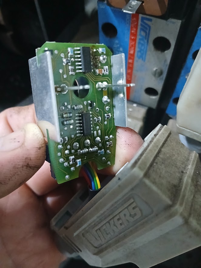

You need to establish the wiring from that third image. Hopefully you will be able to see some numbering for the connectors, perhaps on the back of the lid, in which case 1 is 24V, 2 is GND and 3 is Control. Just based on the colours I would guess the numbering is left to right, but it could be exactly the opposite (the Vickers documentation shows both layouts!). You would need to power up the device and confirm that by actual measurement.
Then connect the PWM-to-DAC device I referred to above to a 10V supply (VIN, GND) and to the plug Control and ground (Vo, GND). The easiest way to test is with one of these devices:
Servo Tester RC 3CH Digital Multi ESC Consistency Speed Controller
(available from many different suppliers). Connect it to a 5V supply, connect PWM and GND to the matching inputs on the PWM-to-DAC device and you should be able to move the cylinder back and forth.
Thanks so much, I have ordered the mentioned components, I will keep you posted with the project.