This is a placeholder topic for “4-digit 8-segment Display Module for Raspberry Pi Pico” comments.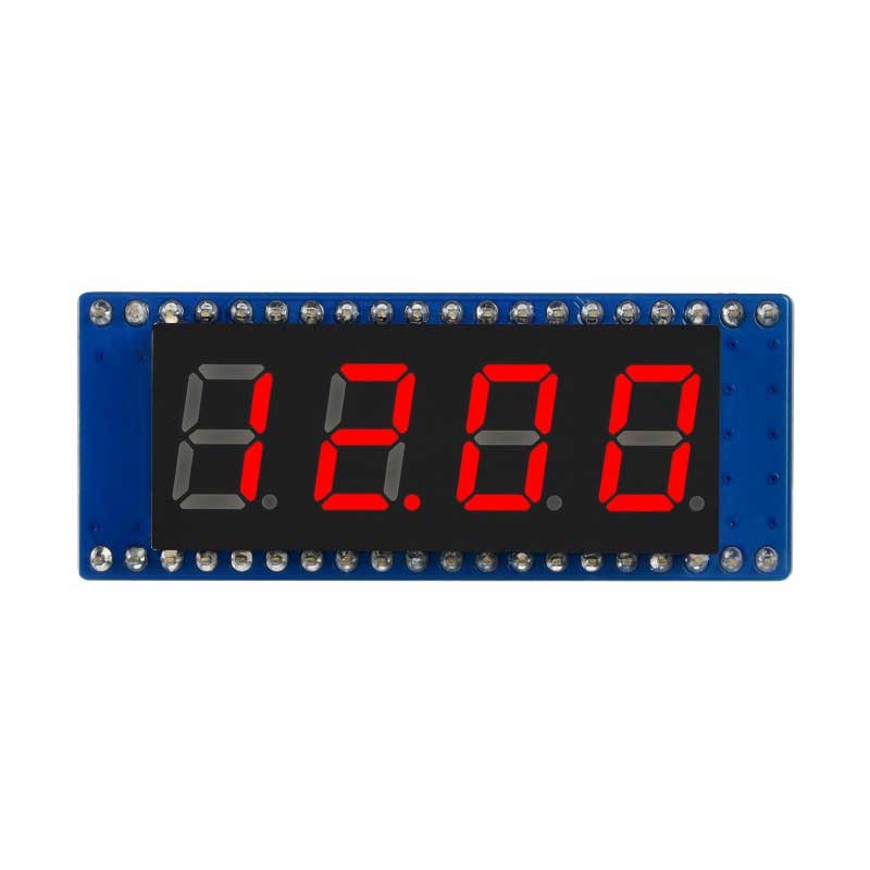
SPI-compatible with standard Raspberry Pi Pico headers and comes with development resources and manual (raspberry Pi Pico C/C++ and MicroPython examples)
Read more
1 Like
Can this display run on 3v3? And can I get it without the socket strips?
1 Like
Hi Rob,
While the display seems to need 5V power, the logic level will be 3.3V to work with the Pico.
Are you looking to use it with a Pico?
James
2 Likes
No I want it as a debugging device on my own 3v3 design. I have a bit-banging SPI output that works at high speed to display a value with little intrusion on the running code.
I think it’s just two 74HC595 shift regs that should work fine at 3v3, so all I can see being a problem is the current-limiting resistor values if indeed they are set assuming a 5v VCC.
I can just make my own PCB but at $6.50 I suppose it’s worth a try.
Rob
4 Likes
I have a completely different question. I bought this little guy because it has the full stop on every digit making it possible for me to show numbers like -9.99 for instance. I started code exploring with micropython seeing how the device works. The sample code is for a stopwatch which quickly updates all digits which seems great until you want to try and display a fixed value like the example provided. Then you realize that based on the number of shift registers and the wiring diagram that it is not possible to display all 4 digits at once, statically, or am i missing something?
The only way I can figure displaying all of them at once is pulsing through them faster than the human eye can detect a flicker and continuously update the display. Am I understanding this correctly?
1 Like
You can display all 4 digits at once, but the digits are multiplexed so you need to continuously update the display with those digits. If the value being sent to the device for each digit doesn’t change then the display will be “static”.
To see the effect you can use the stopwatch example, but display an arbitrary fixed value instead of the seconds value.
2 Likes
Hi @Charles133491 - welcome back to the forums ![]()
Can you show your work? What code are you using to try show a static, multi-digit number? Perhaps we can pick up from there.
The “Demo codes” [sic] example provided on the Wiki seems a little half-baked to me… It would be a shame to have to continuously scan the digits in user-code.
2 Likes
I will clean up the code a bit and put it on Github to demonstrate the issue and a proper implementation.
But, as a consolation prize while you wait;
Looking at the official wiring diagram you can clearly see that W1-W4 is probably the anode for each character.
I am guessing a-h is the cathode for each segment (don’t forget to count the dot) and W1, W2, W3, W4 connects those to ground to display what has been shifted into a-h.
For the display in question (4 digits) you need 8*4 = 32 lines and a common ground to drive all segments independently.
Here is a link to a implementation using the same 2 x shift registers, proving that you at max can only drive 16 LEDs in that config: https://www.radiolocman.com/shem/schematics.html?di=65110.
If you wanted to drive a 4-digit 7-segment display without multiplexing you would need 4x8-bit latches as a minimum. For digit selection you could use a 4-bit latch plus driver, but if you select the right MPU then there will be enough spare GPIO ports to drive the digit select from the MPU, so a 4-bit driver will be sufficient.
The device you have selected is not suitable for driving without multiplexing.
Hi @Jeff105671,
I think we just said the same thing, you just did it a little more fancy ![]()
Not quite. 32 lines only applies if you use a minimal system of latches without shift registers. That would require a chip such as the Mega2560. Even if you use a 2-4 decoder for the digit select then that is just 2 more lines instead of 4, but it is still beyond most available MPUs.
The example you have referred to uses shift registers which can be daisy chained, so you will get away with a lot less than 32 lines, the actual count depending on whether or not you implement blanking while loading the registers. Whatever, it’s a lot less than 32.
Hi @Jeff105671,
I see where the misunderstanding came in. I never even considered using 32 GPIO pins to do this. I was always referring to using shift registers where you use SPI to shift in the data into daisy chained shift registers. The main point I was making that you cannot statically accomplish this on the display in question (CE07914) because it has just 2 x 8 bit shift registers (and 4 of the outputs are not even used on the second shift register), which is where you suggested using 4 shift registers. I think, in future, I need to be more explicit with what I mean when I post.
For the time being I switched to using the 7 Segment Display (2-Wire, 0.5") (CE09446), because as I was implementing the code I realized I needed 3 displays and I have 10 of the CE09446s.
Unfortunately, I had to get creative for numbers smaller than -999 (negative 1 kilowatt) so I used the : (colon) as dot to show for instance -1.34 as -1:34. From the kilowatt you could probably deduce this reports my solar power output and usage. I need a little display to sit somewhere in the kitchen so I can know when it is cheap to make coffee ![]()

1 Like
Great you had a win @Charles133491 - I think your chosen device is probably a far more practical unit for the purpose and far more scalable. It will be easier to produce readable code for and have multiple displays.
I love solar monitoring projects and I’m sure our community does too ![]() consider sharing your progress here, and even share your project!
consider sharing your progress here, and even share your project!
Hi Everyone,
I have modified the example code to allow the display to show a static decimal number for a specified amount of time.
Call it like this
displayNumber = '123.4'
displayTimer = 5   # Display time in seconds (Aproximate)
displayLED(displayNumber,displayTimer)
It will right justify shorter numbers with blanks.
Display an “E” if something goes wrong.
The only other thing you might want to add is a minus sign ![]()
from machine import Pin,SPI,PWM
import framebuf
import time

MOSI = 11
SCK = 10
RCLK = 9

THOUSANDS   = 0xFE
HUNDREDS  = 0xFD
TENS      = 0xFB
UNITS     = 0xF7
Dot       = 0x80

SEG8Code = [
    0x3F, # 0
    0x06, # 1
    0x5B, # 2
    0x4F, # 3
    0x66, # 4
    0x6D, # 5
    0x7D, # 6
    0x07, # 7
    0x7F, # 8
    0x6F, # 9
    0x77, # A (10)
    0x7C, # b (11)
    0x39, # C (12)
    0x5E, # d (13)
    0x79, # E (14)
    0x71, # F (15)
    0x00,  # Blank (16)
    0x00  # Decimal Point (17)
    ]
class LED_8SEG():
    def __init__(self):
        self.rclk = Pin(RCLK,Pin.OUT)
        self.rclk(1)
        self.spi = SPI(1)
        self.spi = SPI(1,1000_000)
        self.spi = SPI(1,10000_000,polarity=0, phase=0,sck=Pin(SCK),mosi=Pin(MOSI),miso=None)
        self.SEG8=SEG8Code
    '''
    function: Send Command
    parameter:
        Num: bit select
        Seg:segment select
    Info:The data transfer
    '''
    def write_cmd(self, Num, Seg):
        self.rclk(1)
        self.spi.write(bytearray([Num]))
        self.spi.write(bytearray([Seg]))
        self.rclk(0)
        time.sleep(0.002)
        self.rclk(1)

def decodeString(displayString):
    displayList=[]
    for character in displayString:
        if character == '0': code=0
        if character == '1': code=1
        if character == '2': code=2
        if character == '3': code=3
        if character == '4': code=4
        if character == '5': code=5
        if character == '6': code=6
        if character == '7': code=7
        if character == '8': code=8
        if character == '9': code=9
        if character == 'A' or character == 'a' : code=10
        if character == 'B' or character == 'b' : code=11
        if character == 'C' or character == 'c' : code=12
        if character == 'D' or character == 'd' : code=13
        if character == 'E' or character == 'e' : code=14
        if character == 'F' or character == 'f' : code=15
        if character == ' ': code=16
        if character == '.': code=17
        if code != 17: displayList.append(code)
    return displayList

def decimalPlace(displayString):
    currentPosition=4
    for character in displayString:
        if character == '.':
            break
        currentPosition=currentPosition -1
    return currentPosition

def displayLED(displayNumber,displayTimer):
    try:
        outputDisplay(displayNumber,displayTimer)
    except:
        print("Error")
        LED=LED_8SEG()
        LED.write_cmd(THOUSANDS,LED.SEG8[14])    # Display E
        time.sleep(0.0005)

def outputDisplay(displayNumber,displayTimer):
    displayTimer = displayTimer* 110  # Convert timer to seconds
    displayString=str(displayNumber)

    # Left Pad with blanks
    noDecimal=displayString.replace('.','')    # Remove decimal point
    stringLength=len(noDecimal)
    if stringLength==3: displayString=' ' + displayString
    if stringLength==2: displayString='  ' + displayString
    if stringLength==1: displayString='   ' + displayString
    print("displayString="+displayString)

    displayList= decodeString(displayString)
    decimalPosition=decimalPlace(displayString)

    LED=LED_8SEG()
    while displayTimer > 0:
        time.sleep(0.0005)
        if decimalPosition == 0:
            LED.write_cmd(UNITS,LED.SEG8[displayList[3]]|Dot)
        else:
            LED.write_cmd(UNITS,LED.SEG8[displayList[3]])
        time.sleep(0.0005)
        if decimalPosition == 1:
            LED.write_cmd(TENS,LED.SEG8[displayList[2]]|Dot)
        else:
            LED.write_cmd(TENS,LED.SEG8[displayList[2]])
        time.sleep(0.0005)
        if decimalPosition == 2:
            LED.write_cmd(HUNDREDS,LED.SEG8[displayList[1]]|Dot)
        else:
            LED.write_cmd(HUNDREDS,LED.SEG8[displayList[1]])
        time.sleep(0.0005)
        if decimalPosition == 3:
            LED.write_cmd(THOUSANDS,LED.SEG8[displayList[0]]|Dot)
        else:
            LED.write_cmd(THOUSANDS,LED.SEG8[displayList[0]])
        time.sleep(0.0005)
        displayTimer = displayTimer-1

    # Once finished blank out the fist left most digit
    # as it's the only one that sticks
    LED.write_cmd(UNITS,LED.SEG8[16])
    time.sleep(0.0005)
Awesome! Thanks for the update @David191372 - I’m sure other users will find it helpful ![]()
I have also thought about calling this as a sub process and not require a timer. That way the number could remain on the display while the main process can get on with something else.
It would just need a way to exit the sub process before displaying a new number or to blank out the number when exiting.
I’ll probably do that if my project has the need. ![]()
Hi Charles
Just spotted this.
Just for the record you CANNOT have negative power.
As a matter of interest how do you calculate power and come up with a negative number.
Just interested…
Cheers Bob
Hi Bob,
You’re right, hehe, unless I violate that 2nd rule…
I use the negative to indicate I am drawing power from the grid and a positive number means i am pushing power into the grid. Instead of using two displays, I take this little shortcut.
Hi Charles
I suppose you could regard that as negative power, especially when you go to pay for it. After all it is money you will never see again.
All forgiven.
Cheers Bob
Bought this some time ago and did not research it enough. The multiplexing is poor design, the need to continually update the display is a waste of processor cycles.
Compared to something like the MAX7219, which will control 8 digits and has a proper SPI interface. Write the data once and it stays there.
This is a rewrite of the library making it more useful including a write number and clear function.
import time
from machine import Pin,SPI

class LED_8SEG():
    def __init__(self, CH=1, SCK=10, MOSI=11, MISO=8, RCLK=9, SPEED=10000_000):
        self.rclk = Pin(RCLK,Pin.OUT)
        self.rclk(1)
        self.spi = SPI(CH)
        self.spi = SPI(CH,SPEED,polarity=0, phase=0,sck=Pin(SCK),mosi=Pin(MOSI),miso=None)
        self.SEG8=[0x3F,0x06,0x5B,0x4F,0x66,0x6D,0x7D,0x07,0x7F,0x6F,0x77,0x7C,0x39,0x5E,0x79,0x71]
#                   0    1    2    3    4     5   6    7    8    9    A    B    C    D    E    F
        self.KILOBIT   = 0xFE
        self.HUNDREDS  = 0xFD
        self.TENS      = 0xFB
        self.UNITS     = 0xF7
        self.Dot       = 0x80
    '''
    function: Send Command
    parameter:
        Num: digit select
        Seg:segment select
    Info:The data transfer
    '''
    def write_cmd(self, Num, Seg):
        self.rclk(1)
        self.spi.write(bytearray([Num]))
        self.spi.write(bytearray([Seg]))
        self.rclk(0)
        time.sleep(0.002)
        self.rclk(1)

#   Call repeatedly to show all 4 digits at greater than 25Hz 0.04ms
    def write_num(self, num):
        self.write_cmd(self.UNITS,self.SEG8[num%10])
        time.sleep(0.0005)
        self.write_cmd(self.TENS,self.SEG8[(num%100)//10])
        time.sleep(0.0005)
        self.write_cmd(self.HUNDREDS,self.SEG8[(num%1000)//100]|self.Dot)
        time.sleep(0.0005)
        self.write_cmd(self.KILOBIT,self.SEG8[(num%10000)//1000])
        time.sleep(0.0005)

    def clear(self):
        self.write_cmd(self.UNITS,0)
        self.write_cmd(self.TENS,0)
        self.write_cmd(self.HUNDREDS,0)
        self.write_cmd(self.KILOBIT,0)

'''
# Example
    LED = LED_8SEG(RCLK=14)
    for i in range(100):
        LED.write_num(78)
        time.sleep(0.04)
    LED.clear()

'''
In the program I used asyncio def to run the display update as a separate process and a global variable as the number to display. Change the number in the program and the display changes.
Regards
Jim
1 Like