This is a placeholder topic for "OLED Display Module for Raspberry Pi Pico, 1.3inch, SPI/I2C (64×128) “ comments.
1.3” OLED Display module an Embedded SH1107 Driver, Using SPI/I2C Bus.
Read moreThis is a placeholder topic for "OLED Display Module for Raspberry Pi Pico, 1.3inch, SPI/I2C (64×128) “ comments.
1.3” OLED Display module an Embedded SH1107 Driver, Using SPI/I2C Bus.
Read moreNice display, I copied the PiicoDev code from the OLED display to make a nice little temperature plotter for the TMP115
Hi Warren,
Cheers for letting us know the PiicoDev code works here too! I’ll update the product page with this info just in case someone is wondering this in the future ![]()
Yes I only used the code for the graph2D and updategraph2D. I had to modify it a little bit.
Hi There, I’m new to using the RPI Pico and have a small (probably silly question).
I i purchase a RPI Pico with stackable headers, would i be able to stack a motor driver like this beneath the RPI:
and then insert a display like this above?
I’m looking to operate a stepper motor repeated and use the display to output the number of cycles
Hi Charlie,
These are both designed to go on the bottom of a Pico, so I don’t think you can arrange them in the way that you want.
I would look into setting the Pico up on a breadboard with an OLED module and motor driver separate. For example here are some affordable parts we make here in Newcastle. You can move to a protoboard if you want to make it more permanent.
Note, this might need some light soldering, but that’s something well worth being comfortable in IMO.
Hi Warren, do yo have a link to the code you used? I’m having trouble getting this display working with my pi pico.
I ran the SH1107 driver code eventually got that to run without errors but nothing comes up on the screen during the demo test.
I think Warren is referring to this guide:
But I’m not sure how to adapt this to a different driver, perhaps you’ll have to dig into the PiicoDev code and pluck out the graphing bits.
Thanks James,
I might look at that one again. I initially looked at that but was getting an “unable to connect to address 0x3C” error
I’ve ordered a new pico with headers to rule out my dodgy soldering skills too.
Hi Chris
Checkout my github see main.py
Hey Warren,
Looks like an awesome use case for those PiicoDev products! We always love seeing what the community creates from our PiicoDev range.
@Chris261572 this could be a good guide for getting what you are after up and running, definitely worth a look at. Wish you the best to get your project working!
Cheers,
Blayden
Thanks a lot Warren,
I’ll have a go with that code tonight and see how I go.
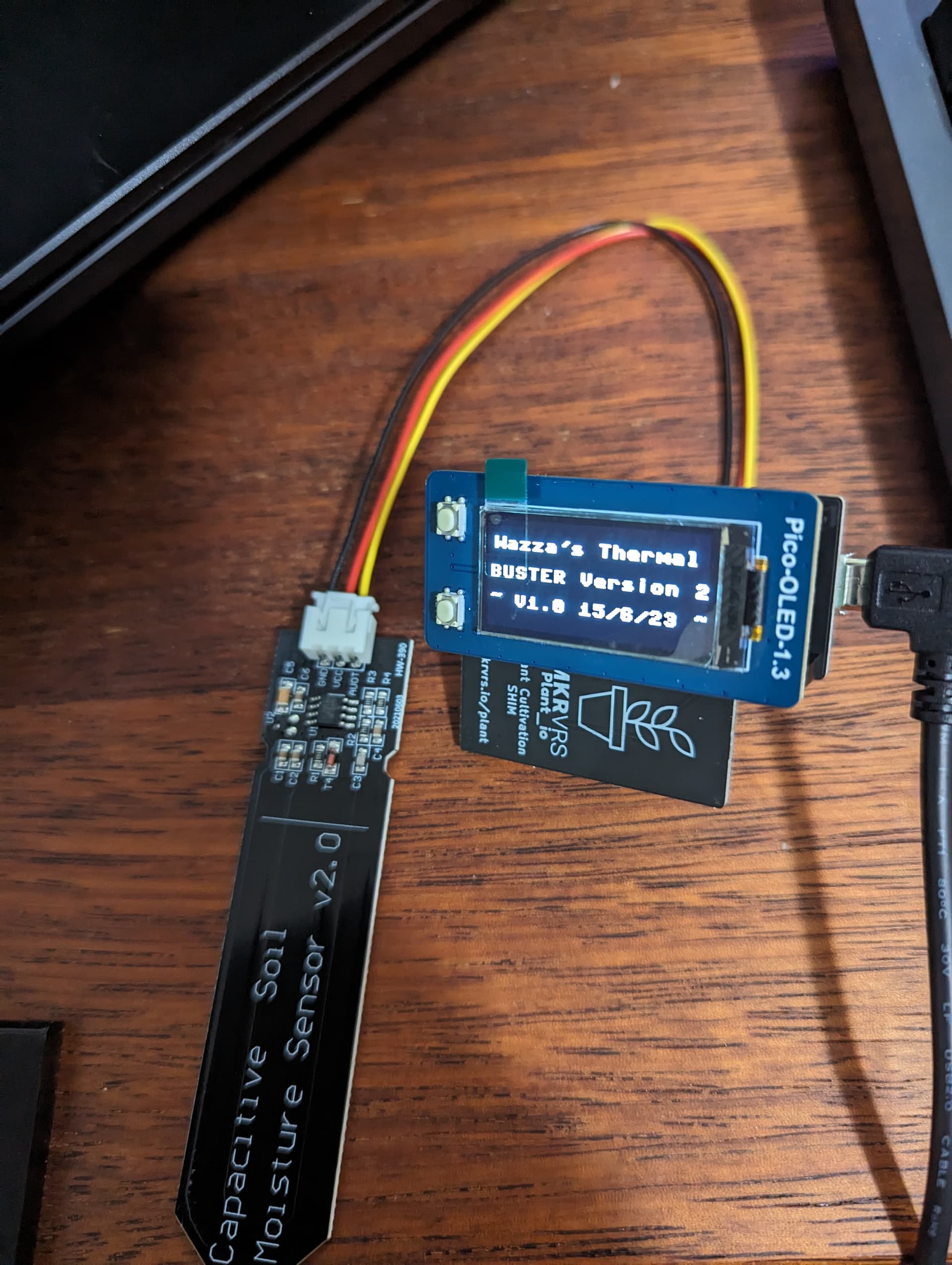
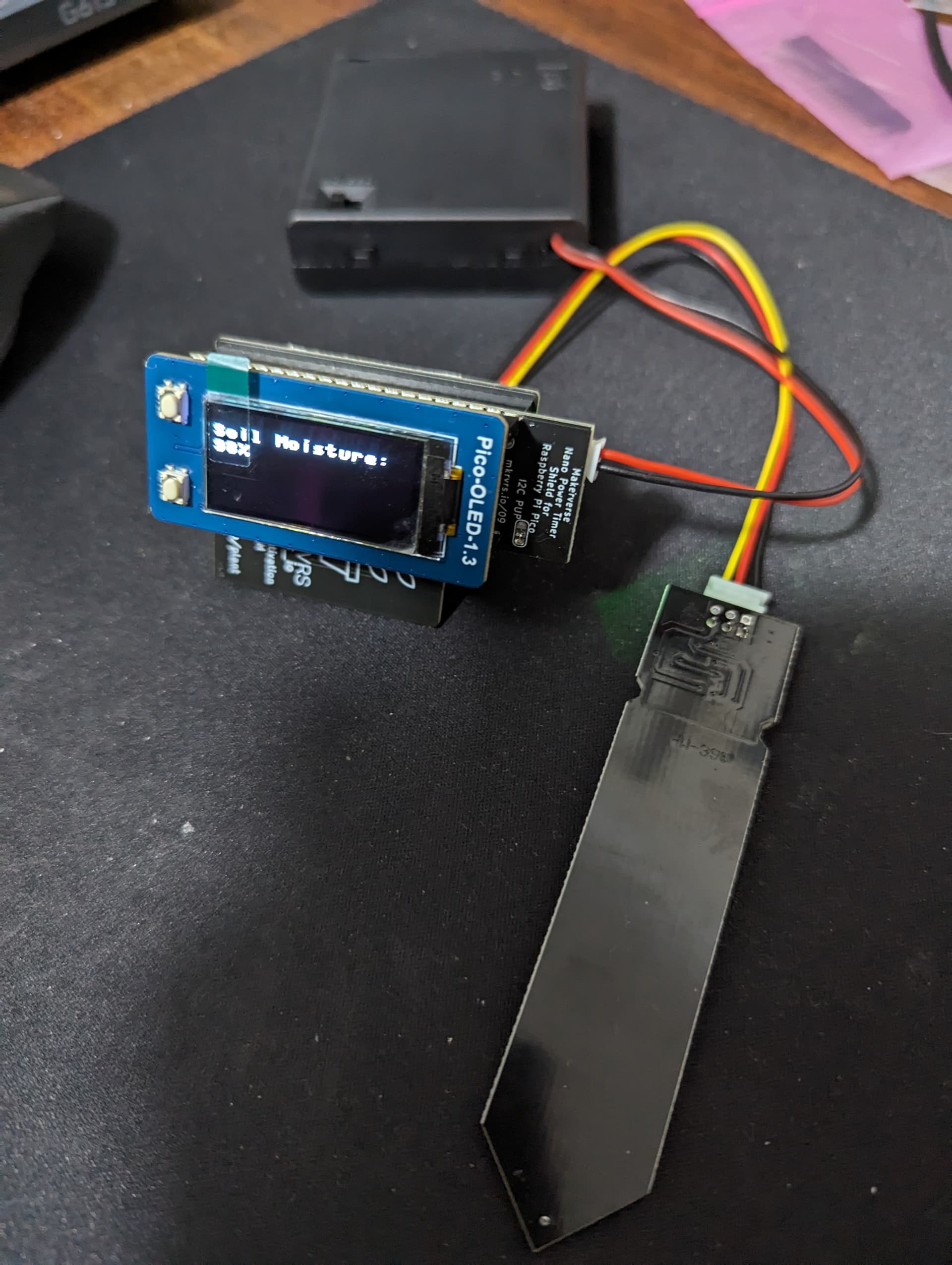
should be a good base as my project is a small portable soil moisture sensor.
Cheers,
Chris.
You’re a good man Warren, that code worked straight away when i uploaded it, a bit of mashing sensor code (and some help from chatGPT) the sensor works great.
Cheers for the help.
Cool! Glad be able to assist!
Good luck with it.
Just adding a similar question to one of the above - I want to use this screen/button combo along with battery power over the pins. Would it be feasable for me to solder the power from battery to those solder points next to the GPIO headers? That seems to be the point of them, I just can’t see that documented. Thank you
Hi @Tristan134105 - if I’m interpreting correctly you want to solder a battery somewhere here, which is not recommended.
The earlier post in this thread features a Makerverse Nano Power Timer which has a 2-pin connector for LiPo batteries and on-board charging
I want to solder a lipo charger board. I know it probably isn’t recommended I just want to know if it woud work ![]()
Maybe… it depends on the hardware you select.
one solution is that you could use this product
Connections for Pico ↔ Charger (pin labels)
5V ↔ 5V
GND ↔ Ground
VSYS ← Diode ← Battery
This will augment your setup with battery charging and battery backup. Use a schottky diode if possible. It will but up to you to manage the battery so that it doesn’t get over-discharged though.
The point of the diode is to prevent power flowing out of VSYS and into the battery which would result in uncontrolled charging at a high voltage.
If you’d like to discuss further, consider opening a topic for this project discussion. This thread is intended for specific questions related to the OLED product.
Hey guys, My little Thermal Buster is a Hit!
I used it the Australian Free Flight FAI F1 Model Aeroplane championships at Naranderra recently and it worked a treat! Even the Chinese and Mongolian international competitors were checking it out. They started to watch us when we launched because they knew we were onto the thermals with the Thermal Buster!
I now have orders for 7 initial units and more to come.
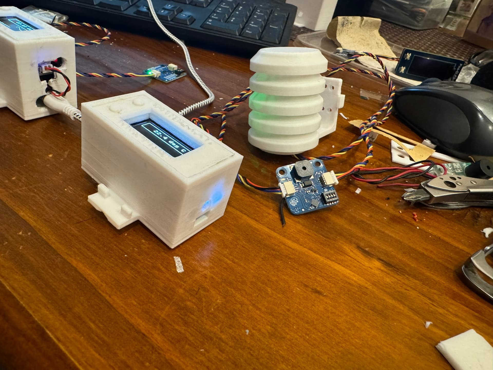
One thing though. I found that the corners of the Pico-OLED-1.3 display are very fragile on the ribbon cable side and can break very easily if pressure is applied to the corner. It needs a spacer glued in underneath to stop this from happening. I’ve broken two displays already resulting in rows of missing pixels.
Another thing I have learned is that the Maker Pico Mini board I have been using for Lipo, buzzer and Maker Port (out of stock at the moment) can be replaced by the Pimoroni Lipo Shim, PiicoDev Buzzer and a PiicoDev breadboard adapter which makes the whole project smaller and cheaper.
I have also 3D printed up the box now so we can rubber band it to our streamer poles on the flying field along with the mini stephenson screen.
What a win ![]() This looks great @Warren249020
This looks great @Warren249020
yes, the glass OLEDs are very delicate at the corners but your solutions sounds super appropriate.
I’m glad PiicoDev could be used to optimise your BOM ![]()
If you’re considering open-sourcing your design or want to do a project writeup, I encourage you to submit your project for curation. There’s even a store credit in there for ya ![]()
And you can get our latest projects and tips straight away by following us on:
![]()
![]()
![]()
![]()