Hello, I have no idea how to wire up the stepper motor I just bought part number (FIT0503) I have limited knowledge and I usually buy bigger stepper motors with driver boards where it’s plug in and play
This stepper motor is small and I am going to cut off the small Jst57sh connector and solder on male jumper cable ends so I can plug them onto the DVr8825 module and then connect to an Arduino.
Of it helps the colours of the wires are black, yellow, white, red.
According to the fit0503 product documentation the leads are:
Red B
White B-
Yellow A
Black A-
According to the DRV8255 device documentation the pins are:
AOUT1 5
AOUT2 7
BOUT1 10
BOUT2 8
where AOUT1 would correspond to A, AOUT2 to A-, etc. However, you indicate you are using a module and the pin numbering of the module probably does not correspond to the chip. Typically, the module pins will be labelled A1, A2, B1 and B2.
Note that it is important that the correct pairing (A and B) is maintained, but it doesn’t actually matter which pair is A and which pair is B.
There is no right way - many different combinations will work, and are often dictated by the cables you have available and the connectors on the devices. You haven’t indicated what the labeling on the driver is, but if it follows the standard Polulu device labelling it would be:
FIT0503           DRV8255
Red B                B1
White B-             B2
Yellow A             A1
Black A-             A2
That’s correct, the terms module and driver in this context are interchangeable. The wiring that Jeff suggested should do the trick. Below I’ve linked a couple of tutorials that you should be able to follow in order to get your stepper motor setup with this particular DRV8825. Please let us know if you have any further questions.
Hi David.
You can’t connect the Arduino directly to a stepper motor. Not enough grunt and it would certainly not like the inductive load. You have to interface via the driver. Study the links Bryce has provided.
Cheers Bob
I followed all of those tutorials this morning but I have a 4 pin stepper motor as you can see in the picture, there are no tutorials I can find for a 4 pin stepper
You will blow up the Arduino if you connect the stepper directly to it.
If your question is about wiring the driver and the stepper to the Arduino, then it is explained in detail in the Makerguides tutorial mentioned above: it is precisly what you are trying to do. Only two wires go to the Arduino GPIO pins - direction and step. The controller converts these instructions into the pulses required for the stepper motor, and at the same time provides the voltage and current needed to drive the motor. You should follow that tutorial step by step and when you run into a part that doesn’t make sense post back with an indication of where you got up to and what the problem is.
I didnt connect the bit with the capicitor and the other bit circled because it should work without it I t right? Since it worked directly from the Arduino??
Quite possibly, if you add any kind of load to your stepper causing it to draw excess current it’d be a good way to blow up your IC or fuse on the board. Without a load, the pins may be able to handle it, but it’s a risky game
The cap is there to deal with back-currents and filtering out voltage spikes, it’s a good idea, but shouldn’t matter too much if it’s not there.
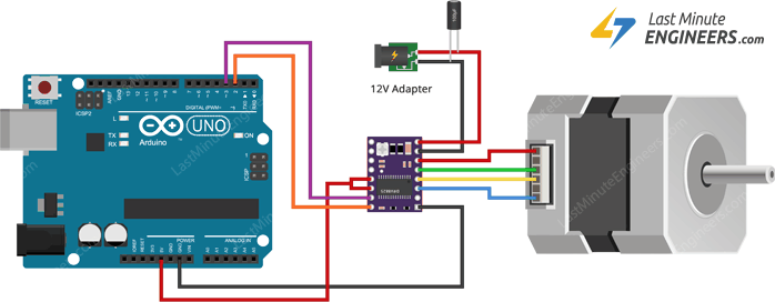
If you hook up your wiring exactly as it’s seen in the image above, and run their demo code, it should run on your Uno. You could give the support team over at Core Electronics a call, although they would be providing the same explanation as provided here, and troubleshooting over the phone is always more difficult as you need to provide exact details of the problem to be able to determine a solution, and there’s no way to be able to share pictures easily.
In this case, I recommend taking apart the circuit you’ve currently put together, it seems to be correct, although it’s quite difficult to tell. Then run through these steps, trying to keep the connections as neat as possible:
Disconnect the Uno from power
Connect the RST and SLP pins to 5V on the Uno (there should be 2 ports side by side on the Uno labelled 5V and 3.3V, either voltage should be fine for a DRV8825)
Connect GND-LOGIC to the ground on your Uno
Connect DIR to pin 2
Connect STEP to pin 3
Finally connect the 12V and your motor to the same side as GND-LOGIC to the matching pins
Following this order listed, there should be minimal crossing of wires and it should be quite easy to hookup your motor. Please let us know if you run into any issues with it and we’ll see what we can do to help
And leading me to these data sheets is like me sending you a Chopin’s symphony and say … There ya go … Just follow that and you will be able to play it