Hi i am using an arduino Uno to try and control a stepper motor although it does not seem to be rotating and instead just humming and vibrating. I have used two different motor drivers and still have the same issue.
I have set up the current limit so that Vref is 0.8V which sees an output to the motor of 1.6V. have also tried increasing this slightly and still nothing which leads me to believe it is something wrong with the stepping input and its timing.
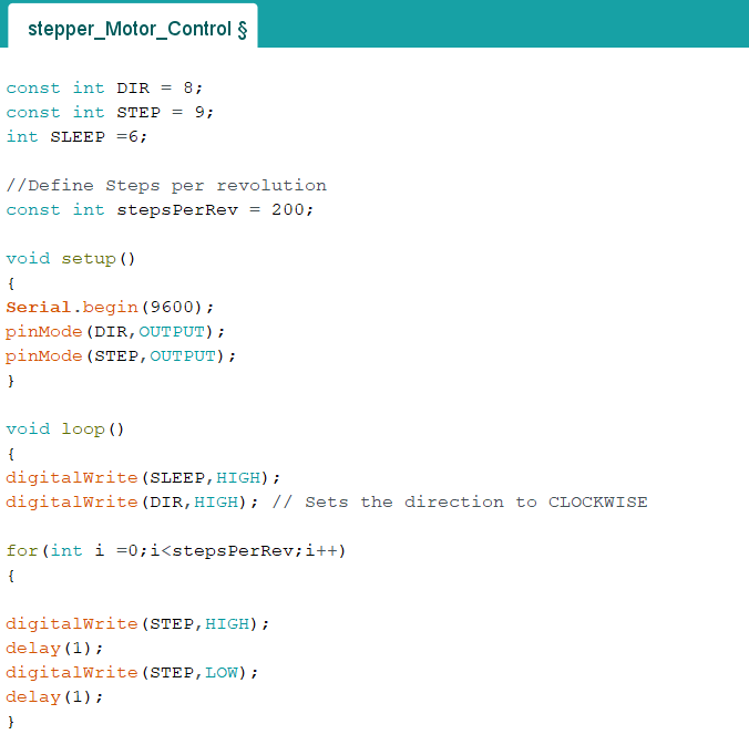
Welcome to the forum! The first thing I noticed with this one is the step speed with the delays you are using.
The delay() function in the Arduino IDE is timed in milliseconds, so I think 1 millisecond is far too low of a time for the signal that will step the motor. I’d try going up to around 250-500ms to start with.
There are a few main ways to increase your maximum step speed:
Use a higher voltage. This lets the current ramp up faster every time you step and allows for a higher average current at high step rates.
Set the current limit to the maximum allowed by your stepper motor (within constraints of the parts you’re using of course)
Ramp the stepper speed up slowly. You can get the stepper motor to a much higher speed if you gradually increase your speed over time (the time delay you have in there) rather than trying to start at the maximum speed from rest.
Decrease the external load on the stepper. The more torque your stepper motor needs to deliver, the lower it’s maximum step speed will be.
I’m not super adept with stepper motors, so I may be a little off base here, but someone else may be able to step in with a more researched answer. Regardless, I hope this helps!
What power supply are you using? That driver requires a minimum motor voltage of about 8v.
The other reason that a motor might just hum is that one pair of the wires to the motor is reversed.
Too low a current limit setting will not affect the motor rotation, so it is OK to be conservative. The motor won’t try to draw max current unless it is under load.
I don’t even know how I skipped over that driver minimum voltage spec…
Jeff is 100% correct though, that one is definitely going to be an issue if you are using the first driver you linked, the second driver should be fine though. And just to confirm, what is the input voltage you are using on that one and what exactly are you powering it with?
I am using a bench top power supply so i set it to 9V for the first driver and then 5V for the low voltage version.
It had something to do with the speed at which the stepping pulse was set at as i found another sample code online that used delayMicroseconds and it worked.
Hi Daniel
Setting delays without specifying microseconds defaults to milliseconds with a resolution of 1msec. For instance if set to “10” the actual delay could be between 9+ and 10 msec. You can see then that setting a delay of “1” would be actually anywhere between 0+ and 1 msec. Could finish up a bit on the fast side for a stepper.
When you reset the delay to microseconds the resolution becomes 1 µsec so at a setting of 1000 µsec the actual delay would be between 999+ and 1000 µsec. far closer to the required 1 msec and probably within range of the stepper.
I hope this may help to explain one of the reasons why your stepper worked when you reset to “delayMicroseconds”
Cheers Bob
Hi guys
Add on to my last post:
I may have shot myself in the foot here with the above post. I just ran that little sketch presented earlier and checked the “step” output of an old Arduino Duemilanove board with an oscilloscope. While there is a jitter evident the best I can make of it is a pulse width variation of about 100µsec with a delay of “1” in the sketch which I would not have thought would upset a stepper too much. If it was not a reversed coil connection the only thing I can think of is that “1” (500Hz) is too fast for that stepper. Daniel did not say what the Microsecond figure he used when it worked. I changed my sketch to 1000 µsec and the jitter seemed reduced but still there.
I think I might have got a bit carried away a bit with theorising and later realised that the timer and clock pulse that carries out the “delay” command would have to be related and the errors not as bad as I portrayed.
I point out that I am only approximating here as my measurement environment would not allow too much accuracy. I learned many years ago to respect the capabilities of the test equipment I was using and work within that. All bits of test equipment have limitations and one must have a fair idea or know what those limitations are. That is one reason that in the real world of accuracy and just as important repeatability even the humble digital multimeter calibration must be checked periodically.
You can hit the three dots in the bottom right hand corner of your post, then hit the pencil to edit your previous posts to remove any incorrect information or typos. We as moderators have the ability to do this too if needed .
ps
@Daniel156236 Excellent, glad to hear that it’s a simple issue with the script, first point of call whenever you get error messages that don’t make sense in an IDE or CLI is to throw them into your favourite search engine, as odds are someone else has hit them before and written up a solution. Also, if you add ``` surronding your copy and pasted code into this editor, it automatically formats it like this best of luck with your project!