Arduino LCD not working

I’m having problems with the LCD experiment, no 15, “Hello world”, in the Sparkfun Inventors Kit.

Can’t get any words on the screen.

Adjusting the potentiometer gives different levels of screen brightness, from nothing, the top line bright, both top and bottom lines bright (top slightly brighter) but still not “Hello, world!”

Have checked the wiring multiple times. And also against the wiring diagram here: https://www.arduino.cc/en/uploads/Tutorial/LCD_Base_bb_Schem.png

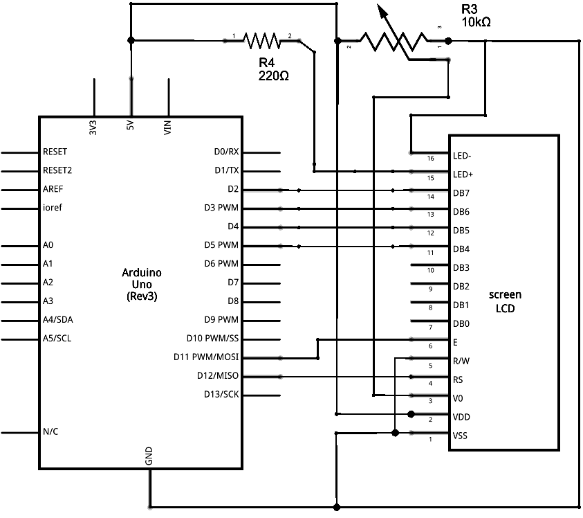
Code is as supplied with the kit, pasted below.

Have also checked against here: https://www.arduino.cc/en/Tutorial/HelloWorld and added a resistor (330 ohms, not 220, but in any case it didn’t really make any difference)

Have also tried commenting out the loop which shows seconds since the last reset.

Any ideas as to what the problem is and how to fix it?


// Load the LiquidCrystal library, which will give us
// commands to interface to the LCD:

#include <LiquidCrystal.h>

// Initialize the library with the pins we’re using.
// (Note that you can use different pins if needed.)
// See http://arduino.cc/en/Reference/LiquidCrystal
// for more information:

LiquidCrystal lcd(12, 11, 5, 4, 3, 2);

void setup()
{

            lcd.begin(16, 2); //Initialize the 16x2 LCD


            lcd.clear();           //Clear any old data displayed on the LCD


            lcd.print("hello, world!"); // Display a message on the LCD!

}

void loop()
{

            lcd.setCursor(0, 1);          //Set the (invisible) cursor to column 0,             

// row 1.

            lcd.print(millis() / 1000); //Print the number of seconds                           

//since the Arduino last reset.
}

Hi Bruce,
The fact that you’ve got those two different contrast bands on the LCD indicates that it hasn’t been initialized correctly. I’ll take a look and replicate your wiring today and get back to you if I can replicate the issue.

Hi Bruce,
I’ve just taken a look at your issue and I’ve built the same circuit and used the code you uploaded and it worked fine for me. There are a couple of common issues which can get you through.

Jumper wires are great, but they’re often prone to dodgy connections and if just one of them is intermittent, it will stop the LCD from working.
It’s a little hard to check your wiring from the picture so perhaps redo it. Often you can be staring at the same thing for so long, you can miss an error. I personally like this guide from Adafruit as it goes through the wiring step by step, and makes it easier to catch a wiring mistake.

Thanks Sam,

Appreciate you going to all that effort. Before contacting you we had unplugged all the connectors and then plugged in again several times, the circuit has been double checked by 2 of us several times too. But I like the Adafruit guide. Will try going through it again closely following the Adafruit guide tonight or tomorrow night…

I was thinking it might be a problem with the loading of the library. But we had reset the board and reloaded the program several times. Rgds Bruce

Sam we have tried again. A couple of times. Still not working. The adafruit guide you linked to has different pin number allocations to the SIK, which we updated. What works is the backlight and the contrast adjustment. But no words. We tested all the jumper cables using an ohm meter, also tested the connections with the ohm meter. All fine. Pretty frustrating that it doesn’t work… cheers, bruce

Hmm, it’s interesting that the wiring diagram you followed didn’t work correctly the first time. Can you send us an email and quote this forum topic and we’ll get this sorted out for you Bruce.

OK, thanks Sam. I’m puzzled as to whether its a problem with the library perhaps not loading properly (although no errors when compiling) or if its the actual LCD that’s faulty which I doubt, or perhaps just a dodgy connection that we haven’t managed to trace. Cheers Bruce

Hi Bruce,
It is definitely strange. When you said you tested the connections with the multimeter, did you go from the solder joints on the Sparkfun board to the solder joints on the LCD?

Actually I’ve only tested the breadboard connections and cables. One end of the multimeter on the end of the cable, the other end on another cable, plugged into the same row of the breadboard. I’ll test the solder to solder joints and advise

All solder to solder connections are fine

Hmm ok, I’ll reply to your email and we can go from there.