I had a lot of fun with the Sparkfun Serial Enabled LCD Kit. I assembled it and got it working just fine.
After a week or so, the screen froze and I can’t get it going again. Immediately preceding that, I’d spent 15 minutes trying to display the result of some text that i assembled by concatenation. It seemed to resulted in a huge amount of data being sent to the display but it was all garbled characters.
Now, when powered up, the backlight comes on, the splash screen does not display, line one is fully illuminated but flickers. Contrast is adjustable using the pot on the ATmega328.
I’ve tried:
Resetting the ATmega328 by grounding the RST pin.
Loading the Hello World sketch which mirrors the serial monitor to the display. It doesn’t work.
Any ideas? Do I need to reboot? Any one ever had to do that?
I did as you suggested, grounded Rx (Yellow) on boot.
Here’s a screenshot my sketch and input at the Serial monitor.
Nothing appeared on the display. I took a photo and will send that separately.
Since it was working fine and is no longer working there’s a fair chance that something was misconnected and/or damaged, but definitely still worth trying to replace the bootloader on the uC.
I soldered jumpers to the ISP test points and managed to successfully reburn the bootloader on the Serial LCD. NOt difficulat when you know what you’re doing.
Then I tried running the Hello World sketch. The good news is, the display doesn’t flicker any more. The bad news is the sketch (modified as you suggest) doesn’t work, characters displayed on the Serial Monitor are not mirrored to the LCD Display.
Should I reload the Firmware? If so, can you get me started with some links.
You could use the usb to serial chip on your arduino to program the Atmega328p on the LCD pcb. Try removing the atmega328p from your arduino, and connecting Rx, tx etc as appropriate to the atmega328p on the LCD pcb.
Also worth taking a look at the arduino schematics. Note that in this special case you’ll want to wire Rx to Rx and TX to Tx to match the arduino pcb connections.
Ps. I’m assuming you’re using an uno or nano. You’ll still be able to do this with a different arduino, but it’s more complicated if you’re at different voltage levels and you should probably just get yourself a USB to serial adapter.
Ppps. You can get a usb ttl module on ebay for under $5-10: https://www.ebay.com.au/itm/383565632148
I’m all for supporting these guys though so worth buying one from Core if you can afford a few bucks extra.
Oliver
I failed in uploading the Firmware to the Serial LCD. Here’s what I did:
Removed the Arduino’s ATmega328 chip;
Soldered jumpers to the Serial LCD’s GND, PWR, Rx and Tx test points;
Jumped the Arduino’s Rx and Tx to the Serial LCD’s Rx and Tx respectively;
Jumped Arduino’s PWR and GND to Serial LCD’s PWR and GND;
Copied the Serial LCD Firmware code from GitHub;
Pasted the Firmware code and saved it as a new sketch in the Arduino IDE;
Connected a USB cable between the Arduino and my computer;
Verified the Arduino’s serial connection was recognised using IDE>Tools>Ports;
Selected IDE>Tools>Board> Arduino Uno;
Clicked IDE>Upload.
Initially Arduino’s Rx and Tx LEDs flickered, then only the Rx LED at intervals of 8 seconds. After 80 seconds, I got this error message from the IDE debugger:
"An error occurred while uploading the sketch
avrdude: stk500_recv(): programmer is not responding
avrdude: stk500_getsync() attempt 1 of 10: not in sync: resp=0xe8"
I tried the same thing a second time, but holding a jumper between Arduino 5v and the Serial LCD DTR test point. Same result.
Yes, those appear to be the correct connections that’d be required. As always, be sure only to apply power after completing and then checking each connection so as not to damage the parts, but yes, the ICSP ports should work.
You’ll need to make sure you reproduce all the connections between the 16U2 and the 328P on the serial board. Follow the schematic carefully (don’t forget to connect Vcc and Gnd).
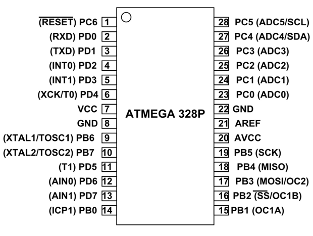
You’ll need to make sure you have connections on the 328P on your serial PCB for at least the following:
1 (Reset)
2 (Rx)
3 (Tx)
7 (Vcc)
8 (Gnd)
22 (Gnd - yes, it’s best to make sure both are connected).
Bryce
Not sure why my previous message got truncated, there was no image.
But I’ve been reading up and I now understand that the 328_DTR must be pulsed low to load a new sketch.
The Arduino’s 16U2_DTR pulses low when data is waiting on the USB cable. In the Arduino that low pulse connects via circuitry to reset the Arduino’s 328, which triggers the bootloader to anticipate data (a new sketch) on the USART.
The Serial LCD board has a DTR test pin. I just need to figure out what to connect it to on the Arduino board.