Which IDE settngs should be used to program the Mini Pro 05.
I have an FTDI USB to serial adapter which works on another bare bones type Arduino, so I believe the USB to serial adapter is good.
I have tried swapping the TX and RX pins but this does not help.
Also tried various Arduino board types, Arduino Mini, Arduino Nano and the Generic ATMega328P processor type.
The IDE runs the compile OK but hangs when it gets to upload.
Be sure to select the correct processor: the “Pro or Pro Mini” option has four options for processor. It will be a 328P. but you need to check that you have selected correctly between 5V 16MHz or 3.3V 8MHz.
Hi Peter
I too have a couple of Pro Mini 5V boards and have programmed with no bother.
I have the Sparkfun adaptor board, Core SKU DEV-13746.
I have a header strip fitted to the Pro Mini but the adaptor can plug in both ways. I think from memory the boards connect with the component sides facing each other. I believe I looked at this and don’t think any real damage can be done by reversing the connector but obviously it just won’t work.
Cheers Bob
Hi Bob;
I have an earlier Sparkfun FT232R Breakout to which I have added male header pins. I am trying with Tx from the 232R to Rx on the Pro Mini and Rx from the 232R to Tx on the Pro Mini.
Cheers Peter.
Hi Peter
Sorry I gave you the wrong SKU. I had another look and it is not the same.
The one I have is as in this kit SKU: KIT-18290 which is the FT232RL apparently
Cheers Bob
PS. Mine already had a female header fitted (a surface mount connector) and I fitted male header pins to the Pro Mini. Worked out which way around to connect by comparing screen printed functions.
Cable is 6-lead straight thru, which turns out to be
DTR-GRN/DTR
RXD-TXO
TXD-RXI
5V-VCC
CTS-GND
GND-BLK/GND
Voltage is selectable 3.3V/5V - set at 3.3V because the Mini is a 3V/8MHz version.
In the IDE I selected Pro or Pro-mini at the board and 3.3V, 8Mhz as the processor. The sketch uploaded without any problem. The 328P doesn’t care whether the power is 3.3V or 5V, so if your board is the 3.3V model then the lack of a 3.3V option on the adapter probably doesn’t matter, but correct wiring and the correct processor speed selection are critical.
Thanks Jeff;
I’m not at the bench today so I’ll confirm settings and let you know if these settings work for me. I also have a 3V version of the USB to serial adapter so I may even give that a go.
Thanks for your suggestions.
Peter.
Robert;
Thanks for your perseverance on this topic. Your suggestions have led me to look a bit deeper at the connections to the Pro Mini I am trying to program.
A bit of background. When I purchased the Pro Mini I ordered and received two identical units. I only ever soldered the headers to one of these and this is the Pro Mini I have been working with off and on over the past 12 or so months. I never got it to work so I would usually put it aside and move on to other projects. But recently I needed to use the Pro Mini for a battery charger project so it was time to have another go at getting code loaded to the Pro Mini.
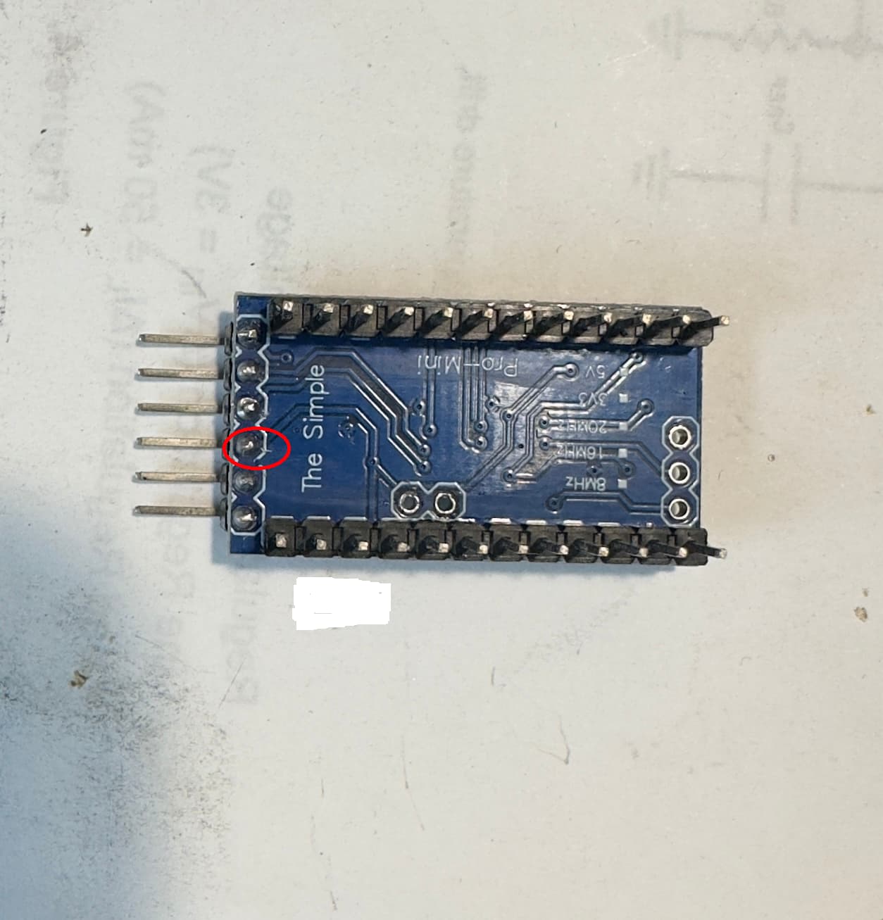
After a few frustrating days this week I finally had enough and soldered headers to the second unit I had received from Core Electronics and tried loading code to the second Pro Mini, and it worked at first attempt. So now I had to look at my soldering on the first unit. You will see from the attached photo that there is a solder bridge from one pin on the serial interface to another part of the PCB, my guess is that the solder mask did not prevent the molten solder from making a bridge to the other pcb track.
So some rework with the soldering iron and cleanup with isopropyl alcohol and reconnect to the USB to serial adapter and I am happily blinking the LED.
The avrdude errors kept pointing to a communications issue with the Arduino board, I had assumed there was something misconfigured in the IDE or the TX/RX connections to the Arduino.
But in the end it was some poor soldering work on my part that led to bad communications between the IDE and the Arduino Pro Mini 05.
So thanks for your helpful suggestions, they helped to get me to have a thorough look at the connections between the USB serial adapter and the Pro Mini.
My Pro Mini problem is resolved by cleaning up previous solder work.
So thanks for your helpful suggestions, in the end they were what led me to look at the soldering of the headers on the Pro Mini board.
Hi Peter
A bit hard to see on that pic. Too much solder and an iron not hot enough will cause bridges. I think to penetrate the solder mask the mask would have to be scratched or something similar.
Cant get a good look but have a careful look at the soldering on 3rd pin from the top of the pic. Solder may not have “wetted” the pad properly.
Good you got it fixed. I have been highlighting the importance of soldering skills for some years on this forum now. This helps prove my point. Come of these faults can be so insidious and mostly difficult to track down. In your case it turned out to be visible.
Cheers Bob