Hi Dick
Yes there are a couple of things that will cause this.
-
The mosfets have failed as a short circuit. The one thing that will cause this is the non existence of a fast diode across the solenoid or the failure of this diode. You will have to check this. There seem to be 2 mosfets on that board. I had assumed the second one has been connected across the solenoid and using the body diode for the flywheel suppression function. This is quite common snd this mosfet will probably have source and gate connected to keep the mosfet part off and just use the diode.
-
The second reason is if the gate capacitor has not been discharged by the Arduino properly. Refer earlier reply where I mentioned this capacitor. It has to be CHARGED to turn the Mosfet ON and DISCHARGED to turn it OFF. Now if it hasn’t been discharged for some reason the mosfet will stay on. EVEN IF THE GATE (or trigger signal) HAS BEEN DISCONNECTED. You can even remove power and when you power up again THE MOSFET WILL LIKELY BE STILL ON. There may be a bleeder resistor of about 10k between gate and source which should discharge the cap. I could not earlier locate a circuit for this board you are using to see exactly what it does so you will just have to have a look.
You can check this by shorting the gate to source. This should turn off the mosfet. If not it probably is shorted.
If I am using an Arduino to operate a mosfet I try to use a device with a very small gate capacitor or use a NPN/PNP transistor driver circuit to supply or sink the required current alternatively there are mosfet driver chips available to do the job. The Arduino is pretty limited in source and sink current capability and don’t forger the mosfet gate is s short to source at switch on because of this capacitor and pretty much a battery at switch off.
Cheers Bob
2 Likes
Hi Dick
Add on to last reply
I found a couple of photos. One is captioned “Dual Mos” which might imply the 2 mosfets are actually in parallel. If this is so you should have a fast power diode across the solenoid. I emphasise “fast” here as a “normal” power diode will not do. Connect cathode to output positive and anode to output negative. ie; effectively across the solenoid. If you don’t have a diode here you will certainly destroy the mosfets. They normally fail short circuit as is what you seem to have here.
Cheers Bob
2 Likes
Hi Dick
Another bit I have just noticed
Please be aware the positive connections are in fact joined on the board. The actual “switch” is in the negative leg. So to check for shorted mosfets measure the resistance from neg input to neg output.
You may be aware of this but I mention just in case.
Cheers Bob
2 Likes
Hi Bob Not sure how to do this, please clarify using the circuit diagram. I am on a very steep learning curve!! I am waiting for info from Philips Electronics re the mosfet switches.
I will also check with the solenoid supplier re the fast diode.
I am assuming you can see the wiring diagram I sent??
2 Likes
Hi Dick.
I would not worry too much about shorting the gate to source. There are some resistors on the board and I am sure one of these will be a gate cap discharging resistor. Was trying to explain what effects this capacitor can have.
To check for shorts across the “switch”, ie shorted mosfet, measure resistance between input negative (-) and output negative (-). The positive connections are connected together by a fat track on the board.
I am only going on photographs of that board but a circuit would be handy. The board has 2 mosfets on it. At first I thought the second one was connected to use the body diode across the solenoid but after looking at the pics I am not sure. They could be connected in parallel.
If the parallel connection is the case you WILL and I emphasise WILL need a fast schottky power diode across the solenoid. Regardless what the supplier says, but I am sure they will agree.
When switching any inductive load a high voltage is generated at switch off by the rapidly collapsing magnetic field. This can be many times the original voltage applied to the load and depends on many factors. In your case, I am only guessing here, it could be 100V or more (this can be measured with an oscilloscope) which is added to the original 12V.
The mosfet on your board is rated maximum 40V so you can see that unless you get rid of the generated voltage spike the applied voltage could be far in excess of what the mosfet is rated at and WILL be destroyed.
If you want the data sheet on your mosfet search D4184
A suitable diode would be MBR20100CT which is 100V 20A schottky. Actually 2 X 10A devices in the same package, common cathode. The centre connection is cathode while the 2 outer legs are the 2 anodes. In use it is common to connect the 2 outer legs together to obtain 20A capability and use as a single diode. Core stock this SKU:CEO7844 or Jaycar ZR1039.
Cheers Bob
EDIT. IMPORTANT.
I just had another study of the pics. Please check and make sure you have got the “V IN” and V OUT connections correct. Your drawings seem to indicate they could be reversed.
2 Likes
Thanks Bob for you help, I am getting a handle on this, a little!
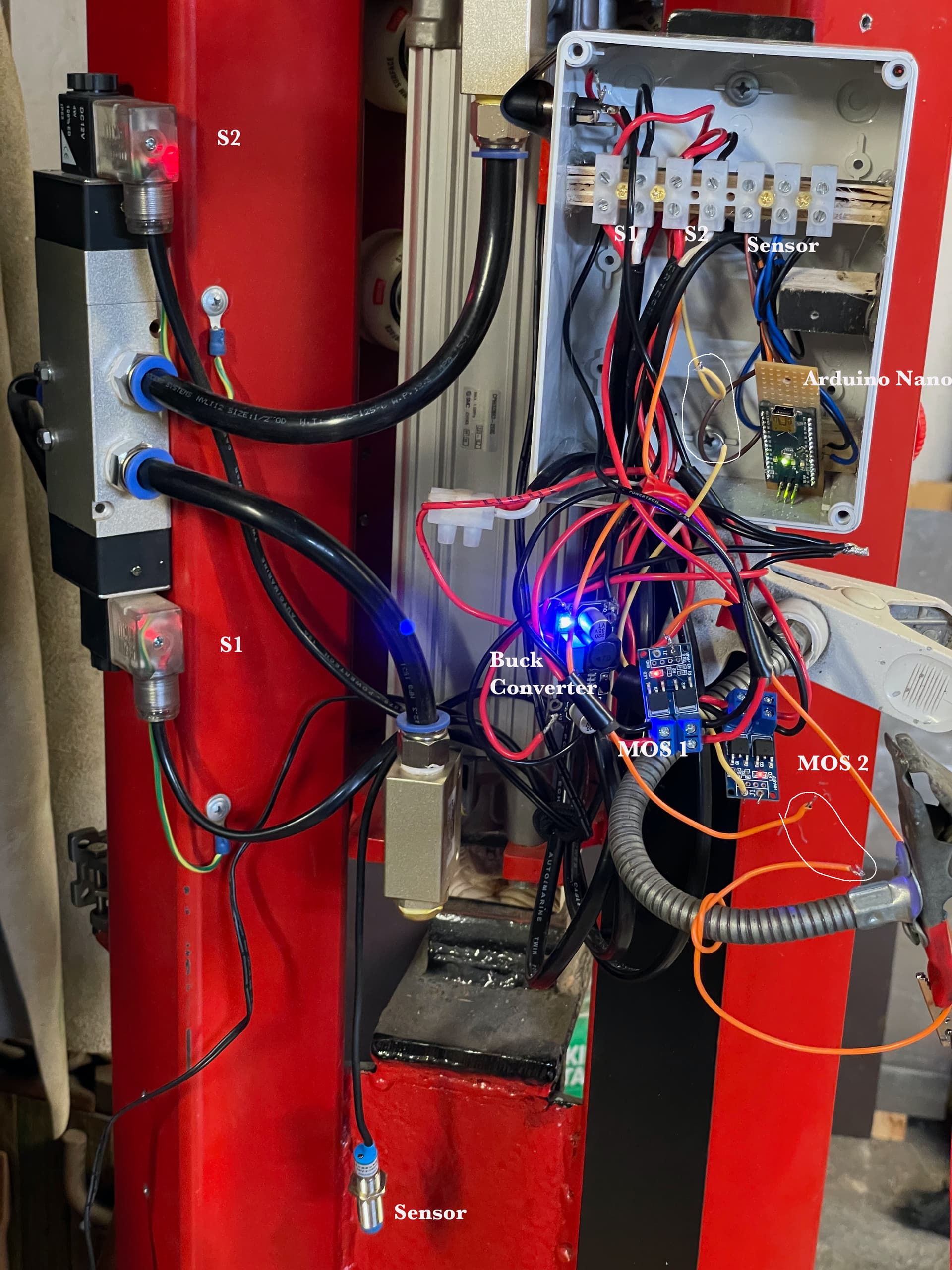
I am still waiting for more info from Controller/ solenoid provider, maybe tomorrow. photos of schematic and actual wiring (it’s a thing of beauty) diagram attached.
Resistance across the common MOS switches, one is 45 ohm and the other is 152 ohm. The readings taken when disconnected from arduino. See circles on photo.
The MOS switches are in parallel. I have checked V IN and V OUT, looks good.
What do you see on the drawing?
Can I connect the diode you suggested across the contacts for the S1 and S2 in the junction box?
1 Like
Hi Dick
I can see the 2 switch boards are in parallel. Each switch board has 2 mosfets. Are these in parallel or is one wired as a diode across the solenoid. The only thing I can find are photos on the web which are a bit unclear on this point. Without further information I can go no further re this.
If you don’t believe me about the diode I can’t help that. If they can provide a circuit for those switch boards that would help but I would not hold my breath. I don’t have one to eyeball so am flying in the dark a bit.
Don’t know what you mean by “common” Mos switches. The 2 different readings spell trouble. I would have expected them to be almost the same. Measure from input -ve to output -ve with everything disconnected from the board. In other words you are measuring the resistance across the switch in isolation. If you have other things connected you could get funny readings due to unforeseen connections.
These are marked on the back of the board so you should not go wrong. Battery connects to V IN and solenoid to V OUT. When I looked at the photos on the web and compared the positions in relation to the trigger connecting point your diagram seems to have the in and out connections reversed Maybe your diagram is wrong.
Ah that photo. Such a dogs breakfast it is pretty useless. Took a while to find one circle. You referred to plural, where are the others. That is no use. To do any meaningful resistance measurements you need to disconnect everything. Refer above.
If that is where the solenoid connects YES. as long as the diode connects to the actual operating coil it will be OK. The diode is in a TO220 package like a power transistor so you will probably have to attach wires to the legs to mount. DO NOT attempt to put a solid component leg and a stranded wire under the same terminal screw. You have enough problems now without creating potentially more.
As a matter of interest. What are you going to with that birds nest. Scrunch all the wires up and jam the lid on??? Best of luck. I think a lot of tidy up may be in order.
Cheers Bob
Just noticed. What is that green line to an earth symbol on your diagram. It is not clear where this connects. DO NOT connect the negative (-ve) wire to earth at this point. If you must connect negative to earth do it at the battery or the battery side of the Mos switches.
2 Likes
Thanks again Bob,
MOS switches
I really have no idea how the switches on the board are wired. But I do know that the four MOS switches I have in my possession have a resistance across the negatives of 270ohm, 54ohm, 785ohm and 111ohm. Measured in isolation. And both the solenoids are on/ascive even without a pulse from the arduino!! That does not sound good to me?
I was hoping the info from the controller/solenoid supplier would confirm that they had a fast diode built in but that is not the case. See below…
Hi Dick,Electrical have advised our units don’t have diodes, only an LED with a resistor and a MOV (Surge Suppressor).He thinks it will be a problem with the controller.
Please let me know if you have any questions.
I will ask them how good/rating the MOV (surge suppressor) …
So I am starting again, attempting to fix the problem and tidy up the bird’s nest!
Core has
Rating 4.5 - 40V and 16A
Your thoughts Please… Is this the answer or do you suggest the fast diodes be added as well??
Is it ok to hot glue the boards to acrylic?
Also there is a reading of 32ohm across the positive and negative terminals of both the solenoids
in isolation. Is this significant? The solenoids are at the top and bottom of the controller They control the compressed air flow to the double action up/down pneumatic cylinder.
The earth connections are on the solenoids on the controller, they are visible on the left of the last photo I sent.
I circled the wires from D12 and D13 to the the MOS switches where I had cut them, but the solenoids remained active!
Thanks again for your input. Dick
1 Like
Hi Dick.
This is a worry. I would have expected an infinity or close reading (OL) with no connection to the boards. With voltage applied there may be a complete breakdown allowing the solenoids to operate. I think both boards are U/S. There has to be a reason why all 4 units have apparently failed. Are you ABSOLUTELY SURE the V IN and V OUT are not reversed. If you have not used a diode that will also be a very good reason for board failure.
YES YES YES. With an inductive load (you can’t get much more inductive than a solenoid) you must use a fast diode to suppress the negative spike at switch off, Particularly when using electronic switching. Indeed a lot of relays have this diode across the coil built in. Extremely important. Forget about the MOV, you still need a diode.
The 32Ω measured across the solenoids is the coil DC resistance and indicates an operating current at 12V of 375mA. This would be a normal reading.
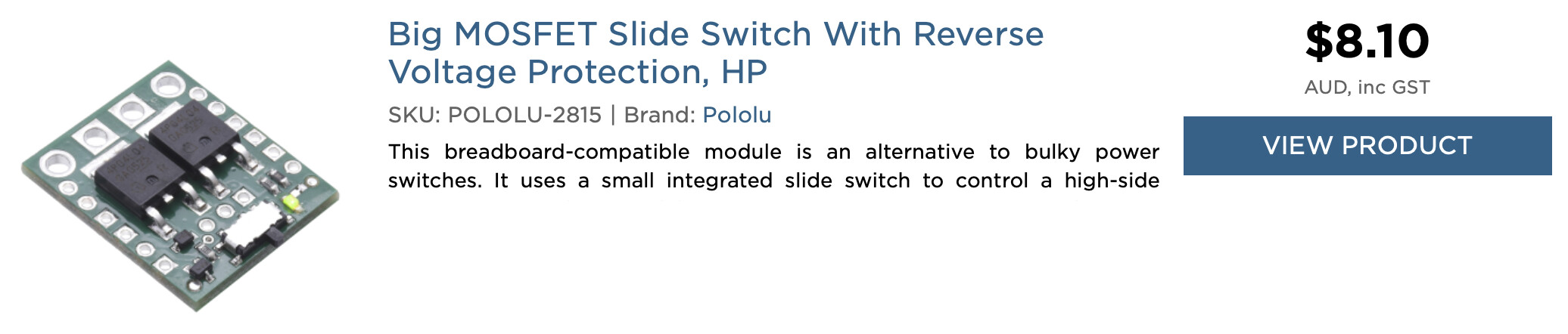
The alternative switch. This is a high side switch as against the low side switches you have (which are US) but you need not concern yourself with the difference. This one has the distinct advantage of being locally available, has a good description on Core web site and has a schematic available. Also Amazon have nil stock of your original.
There is a good description on Core web site, read it. The fast diode is required as mentioned in the blurb. Connect it across the solenoid terminals AT THE SWITCH. Reason being the wiring will have a fair amount of inductance which needs to be quenched along with the solenoid. Cathode to positive, anode to negative.
To switch this with Arduino leave the slide switch OFF and connect Arduino to “ON” connection. Connect Arduino “Gnd” to the “Gnd” pin adjacent to “ON” pin, don’t rely on the through(?) connection of the converter.
I suppose so. I wouldn’t but I am always thinking of maintenance or future changes. If the boards are glued down this will be very difficult. Think long and hard about this. Being home grown this sort of thing is always a distinct possibility.
As long as they are not connected to the negative wire it should be OK. If they ARE connected to the negative wire this would probably account for the solenoids being permanently on. With the proposed replacement switch being high side switching it probably would not matter.
Cheers Bob
Edit;
“this would probably account for the solenoids being permanently on”
Only if the battery side negative is grounded or earthed also.
Bob
1 Like
Thanks Bob, I have ordered the 2x MOS and 2x fast diodes form core today. Still thinking how to sort the junction box maybe a bread board modification that will fit into the one I have. I like the idea of having the arduino accessible to connect with the computer if I need the change the parameters of the sketch.
Q. Is there any chance of you up loading my sketch to an arduino nano, I can send you both, and you send it to me? That way I would be bypassing the computer driver challenge for the moment at least.
Cheers Dick
1 Like
Thanks its on its way…I will post the sketch here, yes? or on another email address…
1 Like