Hi I am building a multi input output system to model the operation of a hybrid power system. With inputs being state of charge for a battery, grid electricity price, solar irradiance and 2 different tank pressures. I was planning to simplify this by using potentiometers and switches as the inputs and led’s and 5V fans as the outputs with some logic I have already determined. Is anyone able to assist me with designing this? particularly the code? I would happily pay for anyone to assist me with this project!
1 Like
Happy to assist with Arduino code, don’t need any payment.
First I would need a little more detail as the what the setup will be and the logic. Any pics you can provide would be a great help.
Potentiometer and switch input is ok direct to an Arduino pin; leds with appropriate resistors to limit the current to 1 to 10mA would be ok direct to a pin. Driving a 5V fan might need some form of driver interface, but still easy to achieve.
Look forward to what you can provide.
Cheers
Jim
2 Likes
Hi Jim thank you so much I appreciate any help I can get. I’m trying to keep it basic for the moment with the intention of making my models more complex as I understand more.

My logic would be as follows:
- If LPT is high AND HPT isn’t high turn on the compressor (Fan1)
- If HPT is high turn on the generator (Fan2) on for 1 minute then check condition again
- If 2 is true AND SOC is not high charge battery (LED1)
- If 2 is true AND SOC is high send power to inverter (LED2)
SOC = battery state of charge indicated by a potentiometer
LPT = low pressure tank high and low state indicated by 2 tactile switches
HPT = high pressure tank high and low state indicated by 2 tactile switches
2 5V relays to control each fan
2 LED’s to indicate power output flow
1 Like
i already have an Elegoo super starter kit
a 10kohm potentiometer (happy to buy any resistance range you recommend)
a dual relay board from amazon https://www.amazon.com.au/gp/product/B07CPVG78K/ref=ppx_yo_dt_b_asin_image_o04_s00?ie=UTF8&psc=1
2 of these 12V DC blower fans from ebay (I do have some other PWM computer fans laying around but I liked that these were small)

And I am absolutely willing to pay for any advice/functioning code. I would be paying for the workshops if they were still happening however the virus seems to have put the workshops on hold =(
Kind regards
Alex
1 Like
Hi Alex,
Had a look through the Elegoo super starter kit (lots of good stuff in there) and after reading your posts the first thing that comes to mind is power supply.
The UNO can be powered from a 7 to 12VDC plug pack or the USB port. As you are using 12VDC fans you could use the plug pack to provide this. The plug pack has 1 plug and it needs to go to 2 places but the UNO has a VIN pin which is connected to the input of the plug pack. (see pic from UNO schematic below)
The UNO input / output pins are 0 to 5V only. Higher voltage (like 12VDC) will kill the pin and possible the UNO. So you will need some interface to drive the fans. The relay board you linked would be ideal because it is designed for 5VDC and the Arduino. So an Arduino pin can be used to drive the relay and the contacts of the relay connect the VIN pin to the fan +ve wire and the -ve wire is connected to ground.
The kit has a breadboard shield that can be placed on top of the UNO. I highly recommend you use this to make the connections so the UNO pins will not be damaged.
So as a starting point.
The project will be powered by a plug pack that can provide 12VDC 500mA (preferably 1A) connected to the UNO DC Power input. The prototype expansion module will be plugged into the UNO. The USB cable will connect the UNO to your PC.
Next you need the Arduino IDE software loaded on your PC and some understanding of how to use it.
Suggest you get this together and try loading the “Blink” program. It simply flashes the LED on the UNO. (connected to digital pin 13) This gives you confidence the UNO can be programmed and is working ok. If you already know all this then all good.
ALWAYS REMOVE POWER WHEN MAKING ANY WIRING CHANGES.
Cannot emphasis this to much.
If you are happy with this let me know. (run out of time for now)
cheers
Jim

1 Like
Hi James
Thanks for the response. Yeah i’m sure I have a 12V dc plug pack lying around. Alternatively I have a benchtop DC power supply I could use. But the plug pack would be a nicer solution if I could drive the relays and arduino with that. Thankyou for the tip of using the shield. I will definately be using that from now on. Yeah i have done the first 12 tutorials in the Elegoo guide including blink. The board works great.
Cheers
Alex
I see that a diode and capacitor is required from the DC plug pack and that is fine. I think I have both. However I don’t understand the 8 pin power connections at the bottom. Are those the pins on the arduino?
Sorry for any confusion I may have caused.
The pic is a clip from the schematic for the UNO. Those components are already on the UNO board.
The pic below gives details of the UNO pins. You can see the power connector and the VIN pin. If you measure the voltage with a multimeter, this pin should measure the same as the plug pack, with a small drop due to the diode. Lesson 2 First Look, part 3. Introduction of the board, shows a pic of the UNO. The VIN pin is labelled but linked with the two GND pins beside it. Maybe this is an error.
To connect the fan you could use two jumper wires (provided in the kit) connected to the VIN and GND pins. If you did that now the fan should operate continuously. This would prove the fan works and the voltage is correct. The next step would be to operate the fan through a relay. The one provided in the kit is very basic and does not have an interface or protection for connection to an Arduino pin (according to the data sheet).
The dual relay board you linked does have an interface and protection.
Very similar to the one from Core electronics, linked below. (pretty cheap actually) I would highly recommend using a relay board like these with interface protection. Opto-isolation ensures the Arduino pin will not be damaged.
Connection is simple. 5V & GND on Arduino to 5V & GND on the relay board. Arduino digital pin (choose any of 2 to 13) to IN1 or IN2 of the relay board. Use software to switch the Arduino digital pin high or low to activate and deactivate the relay.
VIN connected to the common screw connection of the relay, the normally open screw connection connected to the fan. GND from the Arduino to the GND wire of the fan.
I will provide a pic of this later.
Cheers
Jim

1 Like
Hi Jim
Thanks for the clarification. The diode explains why I was getting a voltage drop of around 0.8V at the Vin pin. Can confirm that both fans work using the VIN pin and ground connection. 1 is a bit faster than the other but that is not a concern. The fans draw 190mA each and the DC plug pack I found is rated for 12V and 1.5A I will double check the relays work now.
Thanks
Alex
When responding to these posts you don’t know how much the other person knows and how much experience they have. From your posts you seem to know what you are doing.
The current draw from the fans concerns me when using the VIN pin. 190 + 190 = 380mA. This goes through the circuit tracks on the UNO board. Over time it could damage the tracks. A better solution would to be not use the VIN pin and connect direct to the plug pack. For testing purposes and using just one fan the VIN pin will be ok for now. ie the fan will only be on for a few seconds at a time.
While on the subject of current drain. The 5V pin of the UNO should never draw more than 100mA. The regulator on the board is linear and drops about 7V with a 12V plug pack supply. It is designed to supply 500mA but that would be with a large heatsink. In this case it would have to dissipate 3.5W; the data sheet shows it would reach a temperature of 560 degrees Celsius. It would die if the thermal shutdown did not work.
With this in mind we need to find out how much the relays use when activated. You can use the 5V on the UNO board but a separate 5V supply would be better for testing.
The kit comes with a small power supply that can be plugged into a bread board. But the same conditions apply. I have destroyed the regulator on a board like this by trying to get too much current out of it.
When designing anything electronic, power supply capacity, voltage & current requirements, power dissipation should always be a priority. My rule of thumb is if it will work with a certain level, design it with twice that amount.
Let me know how much the relays need.
Cheers
Jim
PS The pic is a wiring schematic and connections to get the relay to activate the fan. But we need to know the current levels before wiring it up.

This can be used to split the power from the plug pack if it comes to that.
One lead to UNO, the other to a separate 5V power supply, if needed. Provides a way to connect the 12V separate to using the VIN pin and 5V if UNO cannot provide enough.
Cheers
Jim
Hi Jim
Yeah I’m not new to electronics but I am new to arduino. The relays use about 20mA each. For safety I can just run the fans from the breadboard’s power supply. I can just solder leads onto the back of the breadboard’s DC plug pack and make a 12V rail on the breadboard. I might grab one of those cable splitters now but I could also just run the arduino from the 5V rail the breadboards power supply creates can’t I?
Cheers
Alex
Fair enough. I’ll let you handle the electronics, sorry if I have been too simplistic. Some people on this forum are very new to electronics and its quirks. Thanks for letting me know its all good as far as your concerned.
The UNO has 2 main power sources, plug pack via 2.1 socket or USB socket. As it will be plugged into the PC to program, it will not need any other power. The plug pack could be used just to power the fan; the relays via the 5V pin as they don’t draw excessive current. The UNO could be powered by the 5V and GND pins but generally this is not done. There is a mosfet switch that disconnects the USB 5V when a plug pack is connected. If you had it plugged into a PC USB port and the 5V pin connected to another power supply, you would have two 5V supplies fighting each other. Not ideal. Hope this makes sense.
The Arduino is really an ATmega328P microprocessor. The Arduino IDE is an excellent programming and debug interface. To program the micro the Reset line is toggled, running the bootloader in the micro. It then waits for a few seconds to get the code via the TX & RX lines from the PC. If not it begins running the code that had been previously loaded; other wise it loads the code from the PC overwriting whatever was there before and begins running that. All this is handled by the IDE and the design of the UNO board.
The program code has two major routines. setup() and loop(). setup() runs once at the start up, loop() runs repeatedly until power off or reset. I have put together a simple program to switch the relay on and off. The code is C++. It compiles ok but have not done a test with the UNO. Should give you a starting point. I wanted to add stuff to read a potentiometer but internet started playing up.
Regards
Jim
//==================================================================================================
//    Relay Test
//==================================================================================================
/* Aim: Activate Relay for 10 seconds when switch pressed
 *
 *
*/

#define RELAY_ONE           2            // defines digital pin 2 as the relay pin
#define SWITCH_ONE          3            // defines digital pin 3 as a switch

//==================================================================================================
void setup() {
// setup serial port
  Serial.begin(115200);
  Serial.println(" UNO Relay Test ");   // sends the text to the serial port with a carriage return & line feed
  Serial.println(" Press switch to activate Relay ");
                                        // use Serial.print(" some text "); to stay on same line
// GPIO pin setup
  pinMode(RELAY_ONE,OUTPUT);
  digitalWrite(RELAY_ONE, LOW);         // turn relay off

  pinMode(SWITCH_ONE,INPUT_PULLUP);     // places an internal pullup on the pin so it does not float
                                        // pinMode(SWITCH_ONE,INPUT); no pullup

}
//==================================================================================================
void loop() {
  if (digitalRead(SWITCH_ONE)) {        // if switch is pressed statement will be true
    digitalWrite(RELAY_ONE, HIGH);
    Serial.println(" Relay ON ");
    delay(10000);                       // wait 10,000 milliseconds
    digitalWrite(RELAY_ONE, LOW);
    Serial.println(" Relay OFF ");
  }
  delay(100);                           // wait 100 milliseconds before checking again
}
//==================================================================================================
//==================================================================================================Hi Jim
The code seemed to turn the relay on briefly for a period of 100ms every 10 seconds without the switch pressed. Unless the switch was held on in which case the relay stayed on. Unless I wired it up wrong.
kind regards
Alex
I think I have the activation around the wrong way. Using high active rather than what I usually use in this situation, low active. Placing a pullup on the switch input but trying to hold it low and activate when high.
Halfway through writing the post my internet failed, the modem lights went out and would not come back on. Its fixed for now and the ISP is going to send a new modem. So didnt put as much into it as I should have. Anyway …
Put an exclamation mark in front of the digital read as shown below. This mean not true ie false, low, zero volts. It could also be written as if (digitalRead(SWITCH_ONE) == false) {
C++ has so much short hand and a single character can mean a big change.
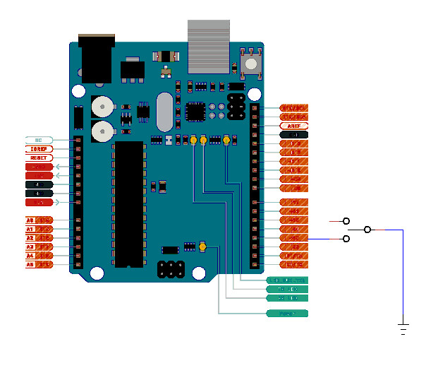
Connect the switch to GND as shown in the pic. This way the internal input pull up holds the pin high until the switch is pressed.
void loop() {
  if (!digitalRead(SWITCH_ONE)) {        // if switch is pressed statement will be true
    digitalWrite(RELAY_ONE, HIGH);
Regards
Jim
This is what I wanted to add before related to analog input.
The pic shows the connection of a potentiometer to Ardunio.
The ATmega328P analog input has a 11 bit resolution returning values of 0 to 1023. Representing voltages between 0V and 5V. The data sheet says a free running conversion can take 13us to 260us.
int position = analogRead(A0); Is the simplest way to read a value.
Serial.println(position); shows us what the value is
The IDE has this routine built in making it easy to use. But it is not the fastest way. Accessing the micro registers directly would be better but not needed for your application.
The above will read the voltage on analog pin A0, convert it to digital and place the value in the position variable which has been declared as in integer.
You could use #define POT_POSITON A0 where the other defines are giving it a human readable meaning rather than just a number.

Note: the A0 to A5 pins can also be used as normal digital pins if needed. But they are the only ones that are connected to the Analog to Digital Converter.
Hope all of this makes sense so far. If not I can explain in more detail. This post will describes some of the program design based on your logic post above. From what I can see the program will need 1 analog input, 4 digital inputs and 4 digital outputs. 6 boolean variables to represent state conditions.
The analog level of 30% is just my choice it can be whatever you want.
The variable names can be changed to what makes sense to you as can the pin designations.
You can use #define statements to name a pin or just use the Arduino pin definition. (A0 to A5, 0 to 13)
Inputs:
SOC Analog - when ADC value less than 300 (30%) set SOC_Low
LPT Low switch active - set LPT_Low
LPT High switch active - set LPT_High
HPT Low switch active - set HPT_Low
HPT High switch active - set HPT_High
Outputs - High ON Low OFF
Compressor (Fan 1) - High when LPT_High & HPT_Low
Generator (Fan 2) - High when HPT_High set Generator_ON, set timer for 1 minute
Charge (LED 1) - High when Generator_ON & SOC_Low
Inverter (LED 2) - High when Generator_ON & SOC_High
Program Variables - 6 boolean.
SOC_Low
Generator_ON
LPT_Low
LPT_High
HPT_Low
HPT_High
Program Loop:
read SOC
check switch activation
process compressor conditions
process generator conditions
process charge conditions
process inverter conditions
check if generator on and timer expired
Let me know what you would like to call the pins and variables and so we can writing C++ for the program loop statements.
Cheers
Jim
Thanks Jim
I had no idea it was so easy to read the input from a variable resistor like that.
Those variable names are fine. I don’t need 2 more variables for generator off and SOC high?
I’d be happy to call the pins anything. SOC_Pin, HPTH_Pin, HPTL_Pin, LPTH_Pin, LPTL_Pin, InverterPin, BatteryPin? I haven’t made up pin names before so I don’t know what the norm is.
Although the tutorials that came with the Elegoo arduino have been great, the one big downside id they don’t explain the code for most of the tutorials =(.
Thankyou very much for your help I have learnt a lot already from you!
Cheers
Alex
No need for more variables. ie If Generator_ON is false it implies the generator is OFF.
Using the momentary switches provided in the kit there may be necessary to hold the switch for the program to run properly. A toggle switch would be better.
The High pressure tank cannot indicate both High and Low pressure at the same time. It will either be High or Low or somewhere in between. Same goes for the low pressure tank. (maybe I am misinterpreting the system here)
Below is a rough cut of the program code. Use whatever may be of use to you. I tried to include some explanation of what the code is doing.
Regards
Jim
//==================================================================================================
//    Hybrid Power System
//==================================================================================================
/* Aim: Model the operation of a hybrid power system
 *
 *
 * created by ????  02 Nov 2020
*/
//==================================================================================================
// #define statements. Whenever the compiler finds the name it replaces it with whatever is on the
// right hand side. It can weven be program code and machine level instructions.
// By using defines the pins can be changed here and the whole program will end up being changed.
// Makes it more effient, you dont have to look through the whole program to change where each pin is used.
// Inputs
#define SOC             A0            // state of charge input analog level (potentiometer)
#define LPT_LOW         2             // low pressure tank is LOW           (momentary switch)
#define LPT_HIGH        3             // low pressure tank is HIGH          (momentary switch)
#define HPT_LOW         4             // pressure tank is LOW               (momentary switch)
#define HPT_HIGH        5             // low pressure tank is HIGH          (momentary switch)
// Outputs
#define COMPRESSOR      6             // switch compressor ON High active    (FAN 1)
#define GENERATOR       7             // switch generator  ON High active    (FAN 2)
#define CHARGE          8             // start charge High active            (LED 1)
#define INVERTER        9             // start inverter High active          (LED 2)

// Global Variable definitions. Available to all program routines.
boolean SOC_Low = false;            // declare as boolean and set false at beginning
boolean Generator_ON = false;       // in C++ all lines need a ; at the end
boolean LPT_Low = false;
boolean LPT_High = false;
boolean HPT_Low = false;
boolean HPT_High = false;

//==================================================================================================
void setup() {
// setup serial port
  Serial.begin(115200);
  Serial.println(" Hybrid Power System ");
  Serial.println(' ');

// GPIO pin setup
  pinMode(LPT_LOW,INPUT_PULLUP);
  pinMode(LPT_HIGH,INPUT_PULLUP);
  pinMode(HPT_LOW,INPUT_PULLUP);
  pinMode(HPT_HIGH,INPUT_PULLUP);

  pinMode(COMPRESSOR,OUTPUT);
  pinMode(GENERATOR,OUTPUT);
  pinMode(CHARGE,OUTPUT);
  pinMode(INVERTER,OUTPUT);

}
//==================================================================================================
void loop() {

unsigned long int Gen_Timer = 0;

// Read SOC and set variable
  if (analogRead(SOC) < 300) { SOC_Low = true; } else { SOC_Low = false; }

// check switch condition
  if (digitalRead(LPT_LOW) == LOW) { LPT_Low = true; } else { LPT_Low = true; }
  if (digitalRead(LPT_HIGH) == LOW) { LPT_High = true; } else { LPT_High = true; }
  if (digitalRead(HPT_LOW) == LOW) { HPT_Low = true; } else { HPT_Low = true; }
  if (digitalRead(HPT_HIGH) == LOW) { HPT_High = true; } else { HPT_High = true; }

// Process Compressor condition
  if ((LPT_High) && (HPT_Low)) {
    digitalWrite(COMPRESSOR, HIGH);
  } else {
    digitalWrite(COMPRESSOR, LOW);
  }
// Process generator condition
  if (HPT_High) {
    Generator_ON = true;
    Gen_Timer = millis() + 60000;           // 1 minute = 60,000 milliseconds
  }                                         // millis() returns the number of milliseconds the program has been running
                                            // easy way to time events, millis() always increases
  if (Generator_ON) {
    if (millis() < Gen_Timer) {
      digitalWrite(GENERATOR, HIGH);
    } else {
      digitalWrite(GENERATOR, LOW);
    }
  }
// Process charge and inverter conditions
  if (Generator_ON) {
    if (SOC_Low) {
      digitalWrite(CHARGE, HIGH);
      digitalWrite(INVERTER, LOW);
    } else {
      digitalWrite(INVERTER, HIGH);
      digitalWrite(CHARGE, LOW);
    }
  } else {
    digitalWrite(CHARGE, LOW);
    digitalWrite(INVERTER, LOW);
  }
  delay(100);                           // wait 100 milliseconds before checking again
}
//==================================================================================================
//==================================================================================================
EDIT: There is an error. Generator_ON is never set back to false. Where digitalWrite(GENERATOR, LOW); is, need to add Generator_ON = false;
Thankyou very much for your help!
I will try to wire it up now. And i’ll look at buying some toggle switches like you suggested.
So just add a line below so it reads
{
digitalWrite(GENERATOR, LOW);
(Generator_ON) = false
}
Is there some way I can make a donation for all your assistance? This forum has been a very powerful learning tool but I feel bad for taking up so much of your time… I hope they start the workshops again soon.
PS
how do you add the code in the pretty box like that?
Alex
1 Like