Project Title: Camera Dew Controller
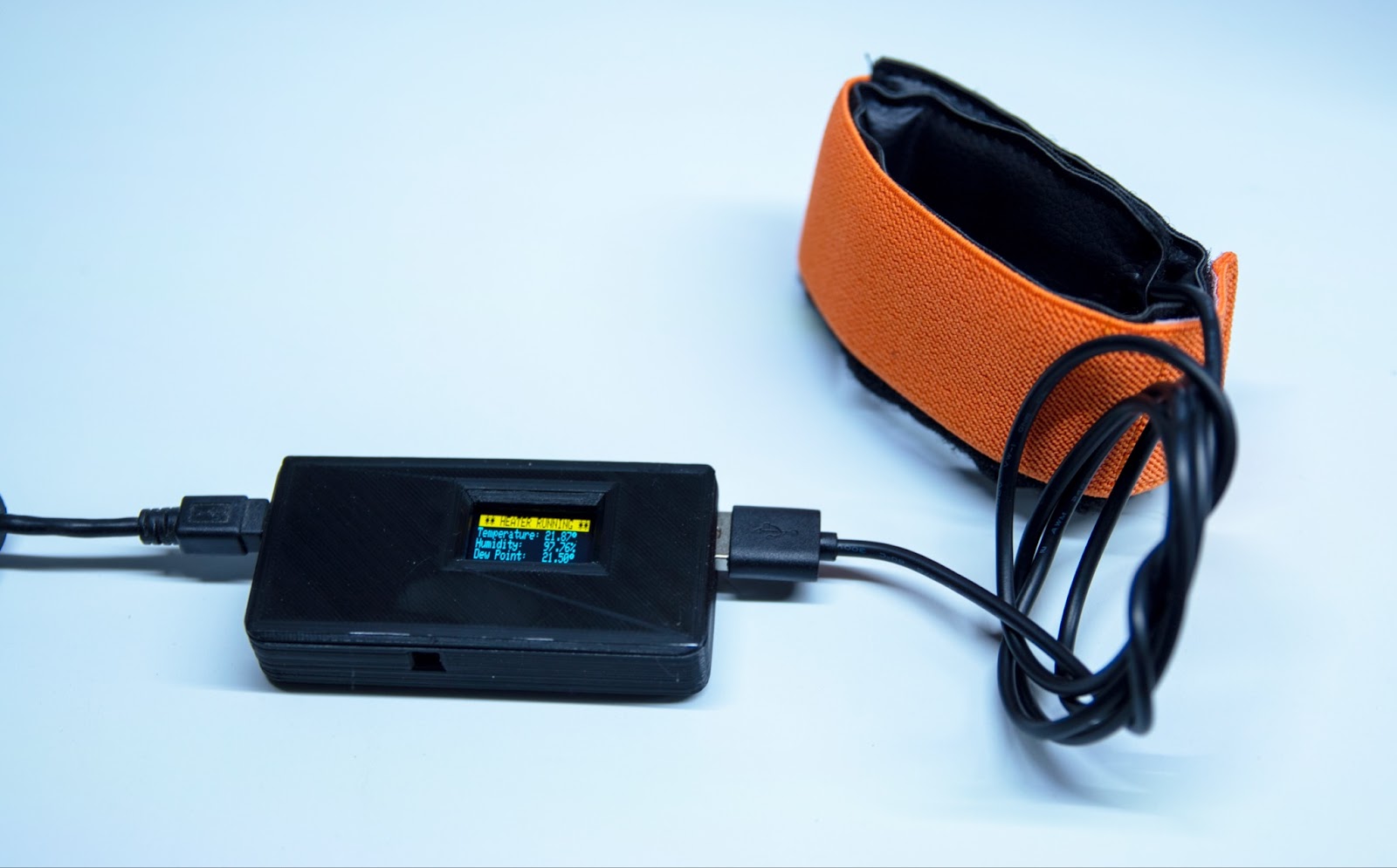
My passion hobby is night-time time-lapse photography and astro-photography / nightscapes. This means a lot of time spent outside in the dead of winter overnight and an issue that I faced was dew condensing on the lens. This is solved by using a heated dew strap that plugs into 12v or USB and keeps the lens warm. This works, but is a big battery drain, so I designed and built an Arduino based system to only activate the dew strap when it was in a dew condition.
An Arduino Nano using a SHT3x SPI sensor to read the temperature and humidity and then calculate when it should turn on or turn off the heating strap.
Parts:

Parts list:
Arduino Nano - Nano V3.0 Board
OLED Screen - 128x64 - Ebay
SHT3x Temp / Humidity sensor - Ebay
Buck Converter - Pololu 5V, 1A Step-Down Voltage Regulator D24V10F5
Mosfet - Fqp30n06l - such as N-Channel MOSFET 60V 30A (P30N06LE)
USB PCB Mount - Ebay
Custom PCB by pcbway
Custom 3D printed enclosure
USB Dew Strap - Amazon
I tended to go with the bulk options when buying parts as I have made dozens of these controllers for similar minded photographers, all reporting excellent results.
Examples:
Here’s a few examples of the dew heater in operation, so you dont actually see the lens fog up, meaning that it is working. These examples were during dew conditions.


Schematic:
NOTE: The part that I used for the USB PCB Mount is inverted so I had to swap GND and VIN.

Data is using the A4 Nano pin for SDA and A5 for SCL. Both the OLEd and the SHT31 use the same bus and are on different addresses.
The MOSFET has GND to the Sink, pin D3 to Gate and Drain connects the GND to the USB socket. The power for the USB socket comes direct from the 5v source, this is due to the heater strap needing a higher current than that that the Nano can provide.
Code:
/***************************************************
  Arduino Nano based DEW HEATER v1.6
  by Andrew Davis and Colin Slack- andrew@brocklesbyimages.com.au

  This code works with dedicated hardware to effect a Dew Heater that will read the ambient temp and
  humidity and calculate the dew point.

  If the dew point gets within 3 degrees of the current temp on the way down
  or 4 degrees on the way back up again, then the dew heater will be turned on
  via D3 running in PWM mode.

  Initial settings are a 100% duty cycle on PWM and 60 seconds on, 20 seconds off.

  Status is read on the OLED.
****************************************************/

#include <Arduino.h>
#include <Wire.h>
#include "Adafruit_SHT31.h"
#include <Adafruit_GFX.h>
#include <Adafruit_SSD1306.h>

#define OLED_RESET 4
Adafruit_SSD1306 display(OLED_RESET);

#if (SSD1306_LCDHEIGHT != 32)
#error("Height incorrect, please fix Adafruit_SSD1306.h!");
#endif

Adafruit_SHT31 sht31 = Adafruit_SHT31();

// Update These Values
//
//
//
int tempdiffdown = 3; //Temp Diff on the way down
int tempdiffup = 4; // Temp Diff on the way up
int onseconds = 60; // Seconds that the heater runs for
int offseconds = 20; // Seconds that the heater pauses for (turns off)
//
//
//
int counter = 0;
bool _switch = true;

void setup() {
  pinMode(3, OUTPUT);
  Serial.begin(9600);
  display.begin(SSD1306_SWITCHCAPVCC, 0x3C);
  display.display();
  while (!Serial)
    delay(10);
  if (! sht31.begin(0x44)) {
  }

  display.setTextSize(1);
  display.setTextColor(BLACK, WHITE);
  display.setCursor(0, 0);
  display.clearDisplay();

  display.setTextSize(1);
  display.setTextColor(WHITE);
  display.println("Automated Dew Heater");
  display.println("brocklesbyimages");
  display.println(".com.au");
  display.print("              v1.6");
  display.display();
  delay(5000);
  analogWrite(3, 255);
}


void loop() {
  float t = sht31.readTemperature();
  float h = sht31.readHumidity();
  double gamma = log(h / 100) + ((17.62 * t) / (243.5 + t)); // DEW Point calculation
  double dp = 243.5 * gamma / (17.62 - gamma); // DEW Point calculation

  display.setTextSize(1);
  display.setTextColor(BLACK, WHITE);
  display.setCursor(0, 0);
  display.clearDisplay();

  if ((dp - tempdiffdown) <= t && t <= (dp + tempdiffup)) {   // This is hysteresis values
    if ( _switch == true ) {
      if (analogRead(3) == 0) {
        analogWrite(3, 255);
      }
      display.println(" ** HEATER RUNNING **");
      if ( counter > onseconds) {
        _switch = false;
        analogWrite(3, 0);
        counter = 0;
      }
    }
    else {
      display.println("    HEATER PAUSING   ");
      if ( counter > offseconds) {
        analogWrite(3, 255);
        _switch = true;
        counter = 0;
      }
    }
  }
  else {
    display.println();
    _switch = false;
    counter = 0;
    analogWrite(3, 0);

  }
  display.setTextSize(1);
  display.setTextColor(WHITE);
  display.print("Temperature: ");
  display.print(t);
  display.println((char)247);
  display.print("Humidity:    ");
  display.print(h);
  display.println("%");
  display.print("Dew Point:   ");
  display.print(dp);
  display.print((char)247);
  display.display();
  delay(1000);
  counter = counter + 1;
}
The code is reasonably well commented and has the included libraries required for the SHT31 and the OLEd screen.
There are variables to be set for the hysteresis of activation. This is defining the band that the heater will run for.
Ie if the dew condition is 10 degrees (at current humidity reading) the dew strap will be turned on when the temperature gets to 13 degrees.
This is the ‘way down’ temp setting.
I have coded this example to have the ‘way up’ hysteresis as 4 degrees, so when the dew heater is in heating mode, in the example above, it will not turn off again until the ambient temperature gets to 4 degrees above the current dew condition temperature, ie 14 degrees in this example.
It’s important to note that this ‘way up’ temperature measurement is against the current dew condition temperature at that time, so if it has changed while the heater is running, it will be adjusted accordingly.
Another feature of the dew heater is that I want to be as miserly on the battery as I can so I have made the dew heater strap run for 60 seconds, then pause of 20 seconds. I have established that the strap itself wont cool down enough in that 20 seconds dwell time to cause any issues, but saves 30% of the power draw.
The code allows for a PWM control of the heater output, however I have not had any issues in running it at max value of 255. This could be turned down to same even more power.
The OLED screen shows the status of whats going on, in near real time with only a 1 second delay for updates. The OLED that I chose is a white/yellow screen, so the top row is Yellow, the bottom 3 rows White. This allowed for the PAUSING and HEATING messages to be reversed out of Yellow bar, to give you a good indication of when the heater is running.
The remaining 3 lines display the current ambient temperature in Degrees C, the current relative humidity in % and the predicted dew temperature in degrees C.
Assembly:
Pretty self explanatory as to how it goes together on the pre-built PCB.
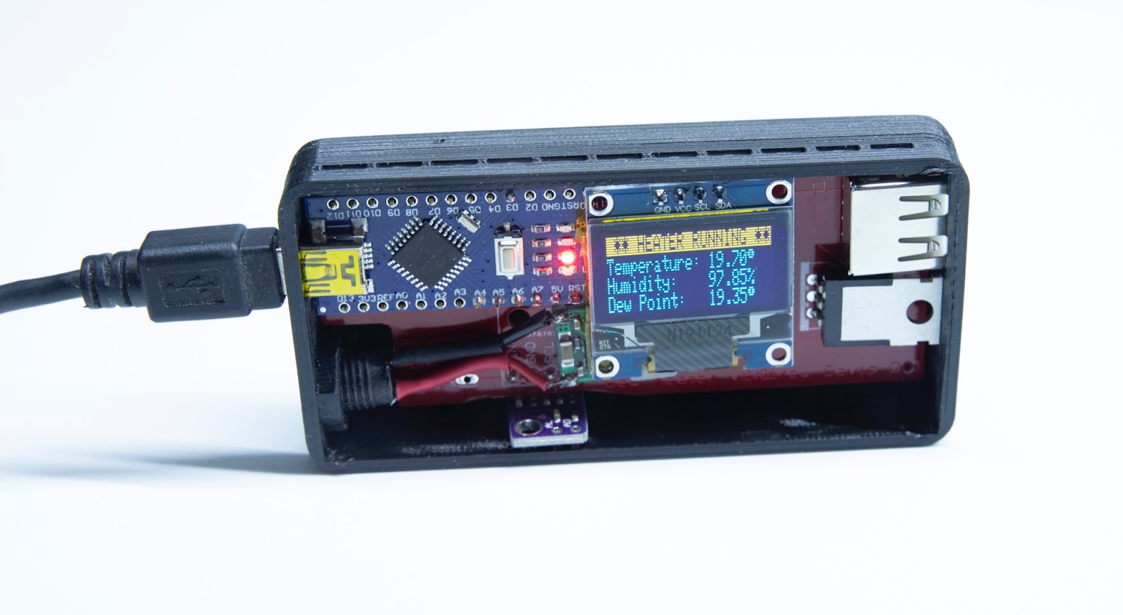
I have turned the SHT31 on the side, so that I can make some more room in the case and so that I can isolate the sensor out a hole in the 3D printed case.
This made room for the buck converter.
All parts solder to the PCB with the exception of the buck converter that is wired in place, however it is not necessary for all use cases.
The buck converter is so that the input voltage can be above 5v and in this example is configured to be used from a 12v source that is obtained from a telescope mount.
When using just on a camera, it is easier to use the dew heater without the buck converter and power from a USB power brick, however this must be specifically wired without the buck converter, it can not be powered via the USB socket on the Nano as the Nano can not provide the required amps for the heater to run.