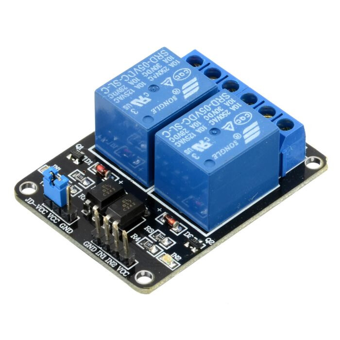
I am using a Raspberry Pi Zero 2 W, and have the Raspberry Pi Camera board [WS-10299], PiicoDev Real Time Clock RV-3028 [CEO8239], PiicoDev Adapter [CEO7690] plus all the other required parts. My aim is to set up the pi to take photos every say 5 minutes over a number of days, continuously over the day and night. I have the script running manually just fine currently. It will be powered by a 100w powerbank out in a field. What I am unsure about, is how to get the LEDs on the camera to switch off with the camera, between capturing images so as to save power. From my limited understanding, I need to buy a relay module, possibly the 5V 4 Channel Relay Module 10A as it has opto-isolated inputs to protect the board from any damage, along with the wiring (3 x female to female jumper wires?). I will only be requiring one channel on the relay but the 5V Single Channel Relay Module 10A isn’t considered as safe, as it does not have opto-isolated inputs.
Can anyone help me to clarify if this set up is correct? Am I on the right path? If not, what should I be buying for my setup?
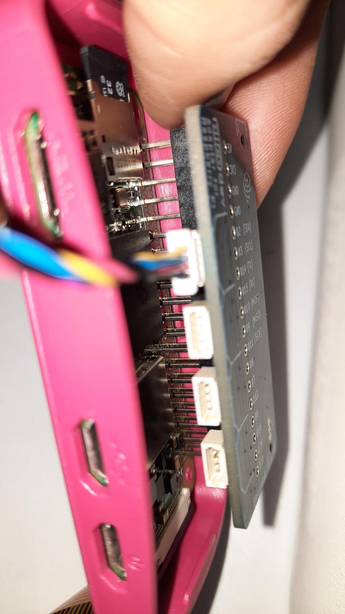
Thanks for your quick reply! And alright cheers, I’m relatively inexperienced so I want to make sure I’m staying on track! I don’t have much to show you diagram wise but will attach my set up so far…keep in mind, I have not soldered the 40-pin header as yet… but yes, I will be needing further help I’m sure down the track lol
Jonesa what code are you using to control the camera module? Are you using a provided library and, if so, are we sure there isn’t some API for the lights in that library?
Pixmusix, this is the script I’m using for running the camera module, currently set to take images every 60 seconds here and works fine. I have used some pre-installed libraries yes, along with others that I have installed. I am a noob but I was under the impression that the LEDs were powered directly from the 5v rail, and once connected, they are always on when the pi is powered on? Which I still find confusing as the LEDs are attached to the camera board, which is plugged into the CSI port.. so initially I did think they weren’t controlled by the 5v rail, but the CSI interface…
It doesn’t look like the LEDs on this camera board have any kind of software trigger from what I can find. The board does have two tiny potentiometers on it that can be adjusted to change the LED brightness if needed, but this can only be done manually.
@Jonesa10 If you turn off the camera with a relay, I think you will need to run picam2.start() each time you power back on to re-establish a connection between the pi zero and the picam.
I also have a suspicion you will need to run something like cam.close() before shutting the camera it down with the relay.
Sometimes in python, but not always, when you start or open something, you need to manually close it.
Here is the picam2 manual and you run a search for the word “closed” or “close()” it pops up a fair bit.
You’re not going to damage something, so nothing to be frightened of.
I’m telling you this incase you run into crazy errors like "ERROR : Can't access device at port blah blah blah because it is already in use". If you see something like that it’s an indication that you didn’t release the device last time. Reboot and have a search stuff like .close() or .destroy() or .release().
Hope that didn’t come off as patronizing, I figure you’re new and I don’t know where you’re at in your journey so I guess there is not harm in throwing it out.
Also, thanks to you Pixmusix yes quite new here so no offence taken at all! I need all the help I can lol So, there has been a development since I was last on here.. I have purchased and attached a 5V 2 Channel Relay Module 10A, 2 resistors between each spotlight and spliced them together as I only have 2 5v on Pi and the other is needed to connect to VCC on relay.
Could you or anyone else, please look and see if this looks right as yesterday I caused my first prototype to fatal short circuit I have not tried to start the pi with this set up as yet lol..
I’ve added a sketchy diagram I made up just now which hopefully makes sense!
My aim is to control the spotlights directly from the pi, hence separating them from the camera board seeing as though I cannot do that when they are physically attached to the camera board.. I have soldered the wires where needed, really well.. I know I should be using a breadboard but yehh.. they are on.
I don’t know what you have done or if the LEDs depicted are the ones on the board.
BUT, as drawn the relay will do nothing. You have the resistors connected to both sides of the LEDs and to only one relay connection effectively putting a short across the LEDs and going nowhere.
Just a heads-up: when we see lines overlapping in a diagram like this, it usually means they’re connected. That’s fine if it’s intentional, but in your current diagram, it looks like 5V and GND are connected, which would be a problem.
Might be worth double-checking the wiring to be safe.
Hi Bob, thanks for your reply. I’ve tweaked the image to reflect more accurately the LED and resistors. The 2 LED wires splice into one to connect to 5v. I still feel this set up is wrong.. I just read “If you want a device connected to the relay to be OFF by default and turn ON when the relay is triggered, you would connect it to the NO terminal. For example, if you want a light to turn on when a Raspberry Pi activates the relay, you would connect the light to the NO terminal.” I clearly don’t have that set up.. The relay module is 5V 2 Channel Relay Module 10A from core electronics.
Now connect the relay common (third connection from left, Blue) to the same ground as the 5V supply to the LEDs.
The way you have them connected goes nowhere. You have to complete a circuit for them to work.
As for driving the relays, Core have not seen fit to provide a schematic so I will not comment. Someone I think reversed engineered this device once but I don’t remember where that is.
I’m a bit confused here.. the image isn’t the best, I know… but the relay terminals from left to right are NO (green), COM (grey) and NC (blue). So currently I have both LEDs negative terminals connected to the COM on relay, should I leave them connected there and then connect the relay COM to the same ground as the 5V supply to the LEDs?
Those hieroglyphics are a bit confusing. Could be read both ways I suppose but due to the complete lack of information from Core You could not be sure.
OK so we will say the Com is grey. To have the LEDs ON when relay activated connect the NO (Green) to the Ground and if you wish to turn the LEDs OFF when relay activated connect the NC (Blue) to Ground.
That should clear that up. Sorry I mis interpreted the markings on the board.