Hi, this is a follow-up to my previous question which is now answered.
I will be connecting 5 buttons, 3 pots and 1 display to my Pico 2W on the Makerverse Protoboard. I will use male headers for the connections. The image below shows how I plan to do it:
Questions:
(1) Is this the right way to create the power and GND channels?
(2) Are the any issues with the wiring plan?
(3) I presume the solder and wires go on the other side of the board. The only thing on this side of the board will be the Pico and the Headers. Is this right?
Thanks
Hi David
Looks OK to me. I would assume all the connections to the Pico are correct. That bit is up to you.
If the display connector is not polarised you will just have to make sure the connector is in correctly. But once connected finally it should not have to be removed except for display failure.
Be aware with these MakerVerse boards the little white lines between holes signify a track and the board is probably double sided, tracks on both sides. That means that if you have to cut a track it has to be done on both sides of the board. It does not look like you have had to cut any tracks so far. It looks like the square pads are individual, no connecting tracks.
Question 3: That should be OK. As I said above if it is the same as MakerVerse boards I have it will have the tracks on both sides.
Cheers Bob
HI David,
Have a closer look at the protoboard when you get it. I think you’ll find that the holes with round ‘donuts’ are connected together. If you look closely some are marked ‘G’ and they actually connect to the ‘4th’ row up, or have a simple ‘solder bridge’ spot to do that easily. That way you do not need to run wires for your ‘GND channel’. On the lower side of the pico pins there is a similar column ( 5th from the right) to create a ‘power’ (3.3V) row (if you need it).
Then where you have orange for the 5 by 2-pin headers you would simply put 2-pin headers vertically where you show the wires. Each header would then be one GPIO(x) and a GND.
For the display you seem to require GND, 3.3, GPIO16 and GPIO17. I would organise that so it sits horizontally with a pin over the side (that would connect to 3.3V), GPIO16, GPIO 17 and the GND.
Holes that have a square ‘donut’ are generally not connected to anything and serve to mount individual components that may be needed.
Hi Dave,
Thanks for your comment, I really appreciate it. But I think what you are suggesting is what I planned to do in the first place. On my diagram I only show 2 wires (the green lines). The blue lines represent soldering and the orange lines show the placement of the headers. There was a colour key below the diagram.
Much appreciated though.
(Other) Dave
Hi Bob,
Thanks for the reminder of that (soldering on both sides). I will remember that when I get to do the soldering (probably later this week).
Cheers,
Dave
I was answering the other dave (lower case d).
You don’t have to solder both sides as these are “plated through” holes, that is they ere connected through the hole to the track on the other side.
The tracks are on both sides and you have to cut both sides when isolating pads. The little white marks between pads signify a section of track.
Cheers Bob
UPDATE:
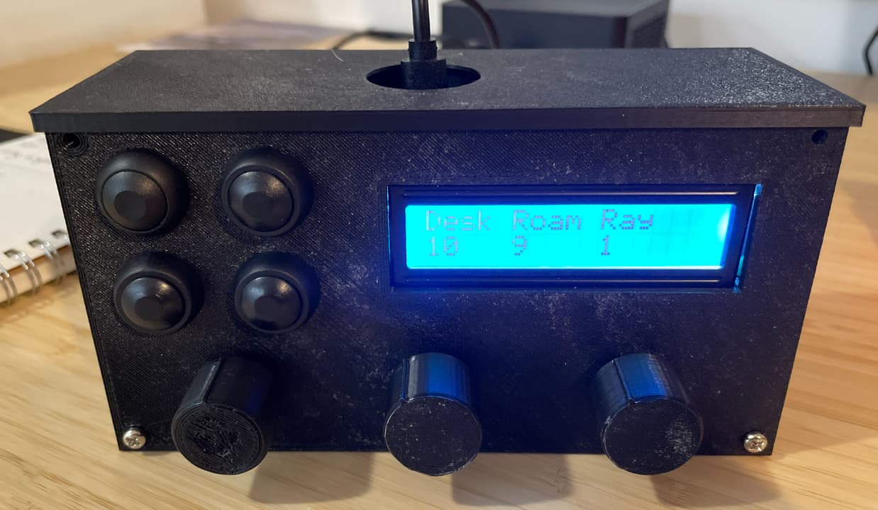
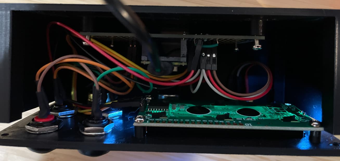
The project is not finished, but I’ve made significant progress…
The soldering is done and this is the project as it currently stands. It is a Sonos speaker hardware remote control: