Help us design the next PiicoDev Module! (PiicoDev Servo Driver)

We’re reaching out to the Maker Community to get your input on our (maybe good, maybe really bad) ideas for our next PiicoDev Module - a PiicoDev Servo Driver

Backstory

We’re spending the next few episodes in our regular engineering show The Factory to take a deep dive on designing a project from end to end: Part selection, PCB, code - the works.
In Part 1 we selected a chip and assembled a test environment
In Part 2 (goes live this afternoon at 4 pm) we program a Hello, World script to drive a servo using the chip.
Which brings us to Part 3: Schematic (and maybe PCB) design. This is where we want to spin some ideas, Dear Maker.

PiicoDev works by connecting sensors and modules together in a daisy-chain. We want to make a new module that is capable of driving 1-3 servos.

Constraints

Connecting boards in a daisy-chain creates a power constraint: the bus runs at 3.3V and is supplied by low-power dev-boards. Certainly this won’t work for power-hungry servos which will happily draw >1A when delivering torque. Also, while there are some small servos that can be supplied by 3.3V, their action is sluggish and they can’t deliver a useful torque.

Ideas

So what can we do? Here’s some of our ideas - tell us what you think! We’d love to hear your thoughts on these, and if you have any of your own. We’ll feature this forum topic in the next episode of The Factory.

Idea 1 - USB-C for Power

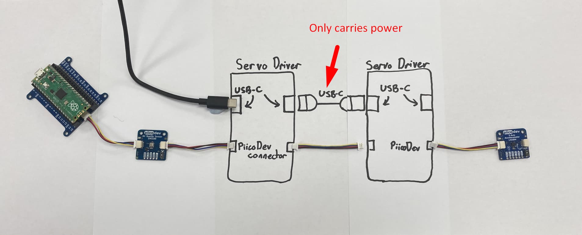
Servo Driver Modules (and other future high-power modules) feature 2xPiicoDev connectors and 2x USB-C connectors. 5V can be brought in via USB-C from an external power source (like a power bank), and USB-C cables can daisy chain connections between multiple high-power modules. If USB-C is used for power-only, then PiicoDev cables would need to be run in parallel to transport the I2C bus.

Idea 2 - USB-C for Everything

This is the same as Idea 1, except the USB-C cable carries all signals:

  • 5V power
  • 3.3V power
  • I2C bus (SDA and SCL)
  • Ground

This topology would potentially allow a user to have some PiicoDev hardware in a daisy-chain, connect a couple high power modules in the middle of a regular PiicoDev daisy chain - all with just one connection between each module. The I2C bus data comes out of the PiicoDev connector, routes through USB-C hardware, and then routes back to the PiicoDev connector.

This is my personal favourite, and what I really wanted to get the community’s feedback on. There are risks here, like what happens if somebody naively plugs a powered servo module into their computer? How could this design be made safe by eg. selecting appropriate conductors within the cable?

Idea 3 - Use an adapter

An adapter could combine PiicoDev signals (3v3, GND, SDA, SCL) with high power (5V, GND) from a USB C connector. The output of the adapter could be some 6-wire harness that can handle reasonable current (this also doesn’t rule out USB-C).

What do you think?

So there you have it - just three candidate ideas for getting power into a servo driver without too much fuss. You’ll notice we have a love affair with USB-C in the first two ideas, and the third is an attempt to get away from that fixation and do something a little more conventional at the expense of introducing another (custom?) wiring harness into the PiicoDev ecosystem.

We’d love to hear your thoughts on these ideas and your own!

- Michael

5 Likes

Hi Michael
Suggestion.
I would not use a UCB C connector for power. You will have a raft of questions regarding the data lines when people try to use that connector as a “USB C” port. Believe me from what I read sometimes here that will happen.
I would suggest using a dedicated power connector, screw terminals??? Anything but a common signal connector. I would also arrange the board so that external power MUST be used to drive the servos. Even if 5V comes from the Pico although more than one board might strain the friendship here.

On another note, are the servo positioning pulses generated by that IC you intend using, I assume so. I would imagine you tell it to say position servo 2 at 110º via I2C or something like that. If that is so is the actual time it takes to do that for each servo going to be an issue and restrict the maximum number of servos possible. That may depend on the individual application I suppose.

That has come up with a device I am experimenting with using the Seesaw Rotary encoder breakout not long released. I thought what a great device with no switch bounce and decoding problems (works well by the way) but the time it takes to recover an encoder position at 1.15mSec is embarrassing for what I had in mind so back to plan A. This will be the subject of another post when I finish a few household chores currently needing attention so please no one hijack this thread on this subject.
Cheers Bob
Quick edit
This probably means I am voting for idea 1

6 Likes

Hi Michael,

This is quite the challenge, I agree! Something for everyone to consider is the alternate modes that USB 3.0 can be put into:

Perhaps pulling the right pins up/down, and/or using SBU1 and SBU2 would prevent USB signals from harming an I2C device, or vice versa.

I do like the simplicity of option 1, some nice thin USB C cables matched to the lengths of piicodev cables would be quite nice IMO.

I think changing the piicodev connector, or introducing a larger type, wouldn’t be a great idea with such an established ecosystem around 4-pin JST SH.

-James

4 Likes

Hi James

I was not talking about changing the PicoDev connector. I said I think it is a mistake using the USB C connector for power only when it would be much less confusing to use what would obviously be a power connector. Simple all round but may not suit the mass production system as far as soldering goes. The alternative would be to provide the connector and holes and let the user do the soldering.
Cheers Bob

3 Likes

When I read this my first thought was something like the Kitronik Compact 16 Servo Driver Board for the BBC micro:bit | Core Electronics Australia with not as many servo drives and much smaller size. Also not limited to just one type of micro, awesome.

I tend to agree with @Robert93820 with respect to use of a USB-C connector to provide power. When building something like this into a project I always prefer terminals or small JST connectors (2.0mm) rather than a USB connector. It makes it smaller and easier to fit in. Getting a Pi Zero to fit into a small box with a Micro USB connector is a pain. You can use the 40 pin connector but that is usually used for something else.

A design with a USB-C socket and a small JST for power would probably work. Allow both options, but might make the board larger.

Cheers
Jim

3 Likes

I vote Idea 1.
But with an alternative power option to just a USB-C connector.

Idea 2 introduces some problems due to non standard use of USB-C pins.

Idea 3 is Idea 1 but on a separate board.

Regards
Jim

2 Likes

I vote idea 1

3 Likes

Wow! Thanks for all your thoughts everyone!

Responses to @Robert93820’s feedback:

Super valid. That’s one of my primary concerns too. We could use some kind of artwork on the board to help people here… like “PiicoDev HP” or something…
The counterpoint to this is that it is an ubiquitous connector that will be supported by computers and USB powerbanks for years to come. Does the convenience outweigh the potential confusion though? It may not even be technically possible, which brings us to @james’ feedback below.

PiicoDev should remain a toolless system. Dedicated power connection, perhaps. But anything requiring a screwdriver will violate the “plug and play” intention.

Yes, the chip does all the heavy lifting in terms of generating pulse-trains for the servo. There is no concern with update rate - I2C is definitely fast enough.

Responses to @james’ feedback:

This is a great table - it looks like Idea 2 is technically possible using Debug Accessory Mode where all digital connections are removed from the cable… allowing us to cram in a few I2C signals.

So I take it that means you’re against Idea 3

Responses to @James46717’s feedback:

Thanks for such a clear vote :smiley:
I’m unsure what your alternative power option means… does that make it a hybrid between Idea 1 and 2?

2 Likes

Hi Michael

No matter what you do it is going to need “tools” somewhere. If you use a cable with a C connector the source end will likely have an A type on it or modify the cable…tools… If you have to make up any sort of cable…tools…irrespective of connector. I know I would much prefer a newcomer to insert a wire into a screw terminal than have to crimp a pin onto a JST connector. Alternative (which I sometimes do) cut a premade JST crimped cable and join a longer length to it. Once again “tools”.
Another alternative for power, use a WAGO style spring loaded push in connector. A bit more expensive but partly removes the “tool” requirement. I say partly because wire has to be stripped and prepared or a pin attached (crimp or solder) to the end.
All in all I really don’t think a small screwdriver is much of a sacrifice compared with all the other tools that may be required.
There are other polarised small connectors and I think pre crimped cables are available for some of them so I stand by my statements about not using type C.
Cheers Bob

3 Likes

I mean have a USB-C connector where the power pins also connect to a JST or header (2 pin) for power.
Allows USB-C if you want and if not power via JST.
Would also allow tapping into the USB-C power if needed.

Idea 2 would be better if it could protect against the scenario where someone may innocently plug in a USB-C device or such.

Cheers
Jim

3 Likes

Awesome topic!! I also vote with Jim (Option 1 but with some changes)

I love the idea of a common PiicoDev power connector while keeping the PiicoDev connector for I2C.

To stay solderless something like an IDC/XT30/MOLEX/Pheonix/Larger JST connector (something that Makers might find around but not so common that could get it at a department store and possibly run into issues with missing data lines…)

This would require some kind of adapter as mentioned in Idea 3 - it could be a simple USB-C, micro-USB or USB-A cable to the connector of choice
AND/OR,
Flesh it out into a full PiicoDev Smart Power module with extra features such as an optional input for a LiPo, AA/AAA batteries, Solar power?) Then the battery voltage could be monitored and react appropriately.

And Bob raises a good point about using tools to pop together the extra cables, if some options are included when the product is released thats perfect - USB-C cables are all too common and come in different flavours as mentioned above, with a dedicated 2-conductor cable all ambiguity hopefully disappears.

Liam

3 Likes

Hey all!

XT30s would suck for this. Despite being smaller than XT60s, they are no easier to pull out (both almost benefit from pliers, a far cry from the ease of JST SH). My vote would be something other than JST PH to prevent battery confusion, but JST nonetheless.

Love this idea. The BQ24195 has boost functionality and a super wide input range (17V IIRC, maybe good for solar?), and a wealth of config options (min/max charge current/voltage to name a few) just waiting to be talked to by an ATTiny on a smart module, worth a look if the engineering team is looking to dig deep. I’m currently testing a dual-mosfet based source selection circuit, I’ll let you guys know if it works as intended. The BQ also has thermistor support, so the PiJuice batteries could fit, though not sure what shuts off when it goes out of range.

An interesting thought is powering the host, the BQ can regulate down to 3.3V, or boost up to 5V on a separate output, giving you options (host type detection even? beefy output for a Pi if batt size/temp allows, less required for a Pico or microbit)

-James

2 Likes

Hang on a bit guys.
I think this started out to be a PicoDev module. It is now getting to be the size of a dinner plate. Maybe step back a bit and regroup.
Cheers Bob

2 Likes

I agree with @Robert93820.
Although not clear from @Michael’s original post, my thought was something:-

  • similar in size to the current PiicoDev modules
  • I2C interface
  • no need for tools
  • separate power connection due to current draw by Servo’s
  • ability to daisy chain together, use existing PiicoDev cables
  • able to drive more than one servo

Suggestions:
PCA9632 4-bit Fm+ I2C-bus low power LED driver would allow up to 4 servo drives.
Servo’s usually have a standard 3 pin header socket, GND, VCC, SIG. Header Plugs.
USB-C power in / out or JST plug 2.0 or 2.54mm.
Core Electronics could provide pre-made USB-C and/or JST cables. Just as the I2C cables currently provided.

Anyway, just a thought.
Cheers
Jim

3 Likes

Fantastic idea for a PiicoDev module. I vote #1 as well, but like several others have noted I would prefer not to need USB-C cables. I would much rather have a standard/common JST-style connector that I can manufacture cheaply myself if I want–something that is much more difficult if USB-C connectors are required. Aside from all the other valid concerns that everyone has raised is the simple fact that projects using this will probably want or need to be small (subjective term, I know), but for the people without cable-making skills it would be necessary to purchase the small usb-c to usb-c cables (at a glance these can be quite expensive) or source cheaper long ones resulting in obnoxious amounts of cable. Given that the PiicoDev 4-pin JST SH cables are cheap and have standard lengths it would be great to see Core Electronics offer matching cable lengths using whatever easy plug you decide on.

2 Likes

Thanks for your input everybody! Keep the ideas and feedback coming :smiley:
I’ve whipped up a prototype and filmed the decisions and discussions along the way - Get the latest in today’s episode when it goes live at 16:00 AEDT

2 Likes