Hi Azula
This might sound like a stupid question but you are putting something white or light-coloured in front of the device to reflect IR aren’t you. There is no indication of anything in the pix and the text is a bit vague
Cheers Bob
I was completely wrong there, this sensor is an on-off affair, and I’ll have to take a closer look at this. Could you post a quick napkin-sketch of your breadboard wiring? I can’t quite make out some of the connections as they are hidden behind other wires. Could you also post any code you’re using, as that might be a problem as well.
Welcome to the forum! This sounds like an awesome project!
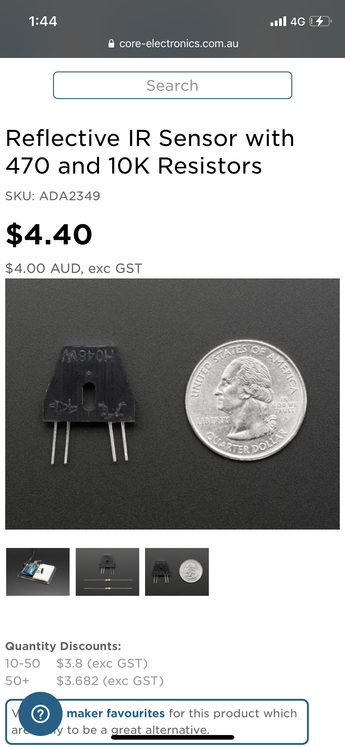
I did some digging and came across this tutorial on Adafruits site using the exact same sensor.
In both examples they are using a board with a logic level of 5V, I haven’t had a play around with the sensor myself but the output pin of the sensor might be driven to a dangerous level for the Pi (the Pins aren’t rated to be able to handle!
I couldn’t find a hard maximum for the Pi’s, you can read more about logic levels here: Logic Levels - learn.sparkfun.com), and the pins also arent able to read analog signals - you need an ADC for that!.
You can read the voltage of the pin using a multimeter if you keep the sensor activated to double-check.
To get it up and running, a logic level converter between the output of the sensor (connecting into one of the inputs of the high side) and the ouput to the Pi with a current limiting resistor for best practice, should get you back on track!
Let us know how you go Azula, I’m keen to see where this project takes you!
Liam.
I think this device is either on or off. Not analog.
I don’t see why this has to run from 5V. Reduce the 470Ω resistor to a value that allows the required current through the IR LED for 3V3 if that is what you are working with. The output should be the open collector of the photo transistor so just return the 10kΩ resistor to 3.3V if that is required. It does not have to be 5V.
Cheers Bob
PS: I have not seen an answer to my previous question, I quote"
I don’t know anything about RPi but you seem to have GPIO Pin 5 connected to Ground. Won’t do much there. Try connecting to phototransistor collector, in other words the other end of this transistor where the 10kΩ resistor connects.
Cheers Bob
I’ve done some reading, and while there isn’t a datasheet on the product, I found a stackoverflow page that suggests using calculating the resistor value based on a forward voltage (unknown in your case but constant for the phototransistor), so you could experiment with gradually smaller resistance values, or use a 10K pot to try and adjust for the differing supply voltage of the Pi.
 thanks in advance