Help with WLED on an esp32

Hi,
Posted a while ago while getting setup, and have run into a really confusing issues.

I setup like this

I installed WLED through their installer site.
Once it was all wired up I hooked it up to the power and it all lit up in plain white. (I did a small dance of joy at managing that)

I then tried to login to the WLED and it wouldn’t load, checked my network and the WLED wasn’t showing up.
I plugged the micro USB into my laptop and was able to access the WLED controls, but I had to disconnect power to the LEDs for it to connect, because if I had the power and the micro USB connected no lights lit up at all
I then setup the pattern/playlist I wanted (fire pattern), set it to autoplay on boot, and saved.

Unplugged the micro USB and reconnected the power, and then half the lights were flashing random colours. (The first half of the lights like power wasn’t getting all the way through, but it had originally lit up with full brightness all the way through)

I disconnected the power and reconnected the micro USB to adjust the programming again.
Reconnected the power and it was flashing a different random pattern on only the first half.

Frustrated, I disconnected the power, and went to bed hoping to go fresh today.

Well… Hooked the power up again today and nothing… Not a single weak flashing light.

This is what it looks like right now.


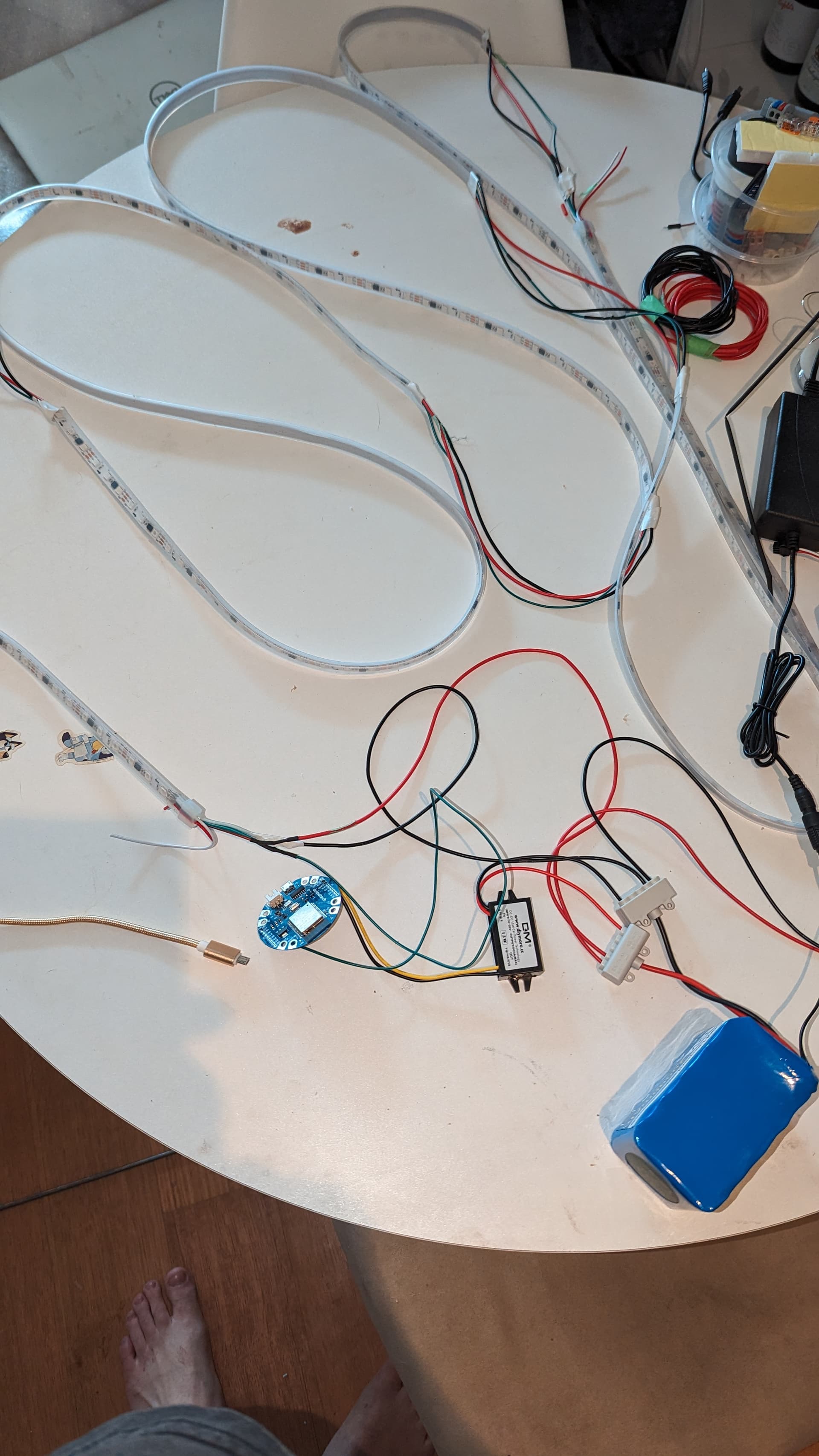
The esp32 is a duinotech wearable. (Bought after I had issues with the esp8266 I had originally)
There are 3m of WS2811 LEDs
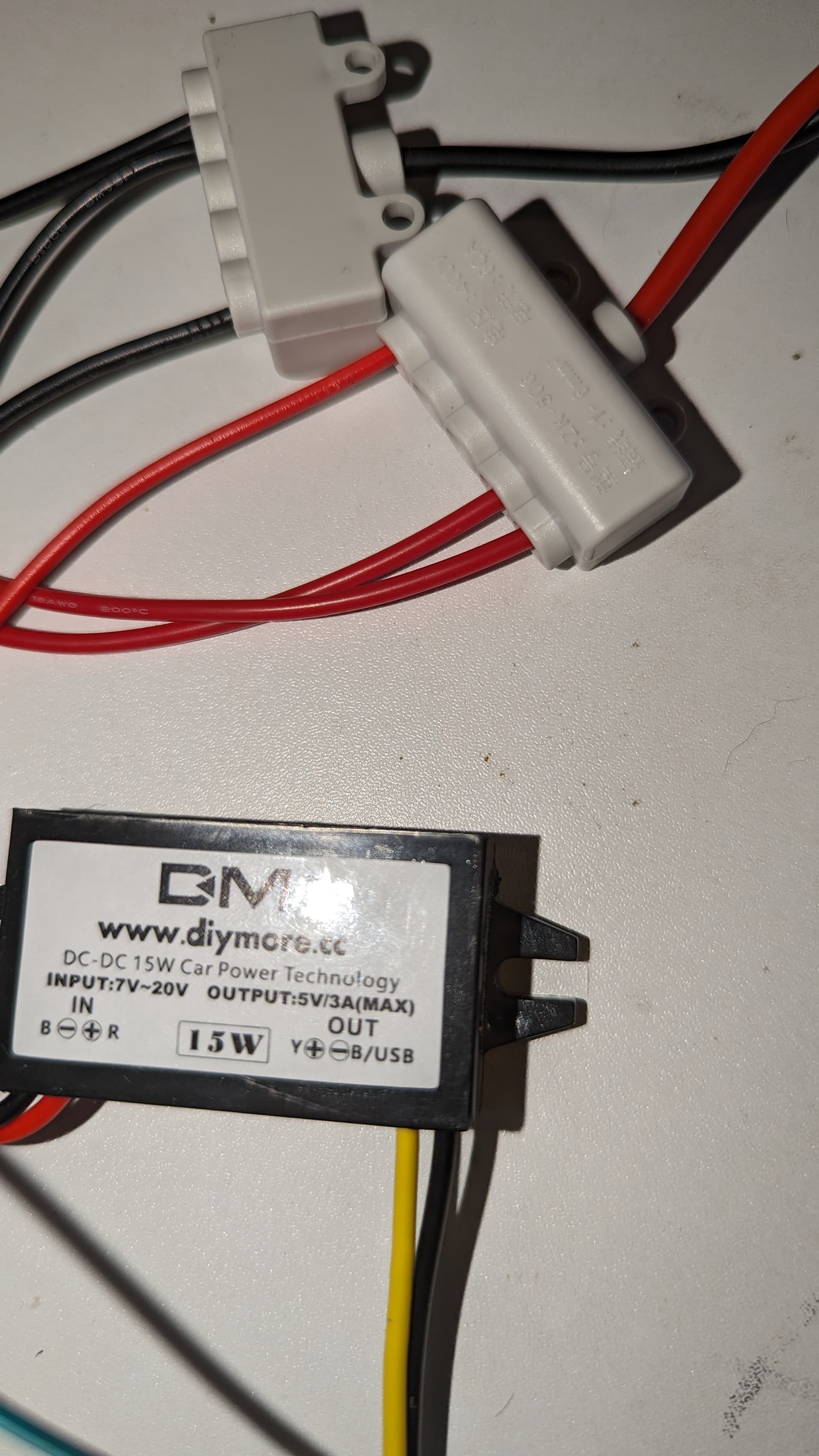
And a 12v to 5v converter from the battery to the esp32

What the hell has happened? What can I do?
Why won’t the esp32 connect to my wifi without the micro USB?
Why did half the lights drop out after they all lit up the first time?
How do I fix this… I am at a huge time crunch at this point.
Please please help

It appears from your diagram that there is no separate ground between the ESP and the LED string. You are relying on the 5v/12V adapter not being an isolated type, so it provides the ground connection. If it is an isolated adapter then the missing common ground could explain the symptoms.

1 Like

Hi Matt
Check your ground and data connections. On your drawing you show + (Red) on the centre connection all the way through but the other Gnd and Data connections reverse a couple of times. This would really play games with your attempts at driving the LEDs.

If the input to strip 1 is correct:-
The output from strip 1 and input to strip 2 is correct
The output strip 2 and input strip 3 are reversed with Gnd
The output of strip 3 in reversed and input of strip 4 is correct
The output of strip 4 is correct and input of strip 5 is reversed.
Cheers Bob

1 Like

Thanks for the quick reply guys.

The colours in the top diagram are a bit off, but on the actual wiring the red green and black are all connected to the correct pads between the led strips

Are you saying I need a data line from the last strip back to the esp32? And a ground from the esp back to the battery (or the step down)?

Do I need something else on the chip to make the wifi work? Or is that the absence of a return ground from the chip?

The ground or -ve lead powering the LEDs must be directly connected to the ground or -ve lead powering the ESP. It doesn’t really matter where you make the connection, as long as it is a direct connection. It is possible that the connection is occurring between the input -ve and the output -ve of the 5V/12V adapter (and then through the ground distribution block to the LEDs) but that’s not guaranteed. Much better to run a direct connection.

It is difficult to see what LEDs you are using from the pics.
Can you provide a link to these, or a part number of something ?

The first pic shows WS2811 DC12V.
Wiring diagrams in the datasheet for the WS2811 chip show 33 Ohm resistors in the data lines.
A 104uF cap is also needed in the supply to the LEDs.
Maybe these are included in the LED strip, it is hard to see what is actually on the strip.

The LED strips shown in the first pic seem to be WS2812B addressable LEDs.

I think you have 60 LEDs, the data stream takes time to traverse through each LED. Maybe the micro does not allow enough time for the whole LED strip to be programmed. I’d try a smaller number of LEDs, like about 6 or so. Add more as you get it working.

The other problems you describe sound like power or grounding issues. If the supply to the micro is not good enough or has too much noise, could mean no WiFi and random LED lighting.

More information is needed, maybe some close up pics of the LEDs.

Anyway, hope you get it working.
Cheers
Jim

Hi Matt
The connections between strip 2 a n 3 are actually correct. It is the colours that are reversed.
The connections Data and Gnd between strip 3 and 4 ARE reversed if wired as shown irrespective of colour.
The connections Data and Gnd between strip 4 and 5 ARE reversed back again if wired as shown. In other words strip 4 has Data and and Gnd connections reversed.

That is if it is wired as shown. If this is not the case then why isn’t it the same.

Definitely NOT.

If the Gnd on the converter is not connected directly through then YES you do need to connect both grounds together. It is the usual thing to do anyway to minimise any grounding problems

While on the subject of Data lines. There should be a small arrow showing the direction of data “flow”. These arrows should all be pointed in the same direction, that is away from the ESP32. This is important.

If that arrangement is two and a half strips then it is possible that one strip is connected backwards. I would suspect strip 3 in that diagram.
Cheers Bob
EDIT. If that diagram is an actual pictorial of what you have it looks like the strips have been cut across the middle of an actual LED. If that is the case anything could be happening at this point. I don’t know exactly what strips you have but the ones I have on hand have a definite cutting point indicated and it is NOT across any LED.

1 Like

Possibly, but you won’t know until you get the whole strip working properly and can see whether there is any noticeable change in brightness over the length. If you do connect to the other end you need to determine whether or not you also need to disconnect the strip at the centre - this will depend on the exact variety of LED strip that you are using (5050 is just a size indication, and it is possible that your particular strip does not support feeding from both ends simultaneously). But that consideration can wait until you get the strip (or at least a part of it) working properly.

Hi Jeff
Matt is talking about the Data line. That is definitely not on, one end only. He already has the 12V connected to both ends. That is OK as all LEDs are in parallel anyway as far as the LED power is concerned and doing this would help even out the brightness.

I do agree though that he should start small and progress from there. Even go as far as disconnecting all sections and reconnect each one in turn which should isolate any problem to a particular section. Would have to adjust any sketch in operation as he goes to reflect the number of LEDs in circuit.
Cheers Bob
Add on:
The only info I can find on that 12V - 5V converter is here

No info nn whether the negative lead is common or not. Better and safer to assume not.

So, just a clarification.
The diagram was just a first draft using pics I had, so the chip and LEDs in the pic aren’t what I used. The program I used to do the diagram also kept snapping lines to the wrong spot and it was a pain to fix, so I didn’t.

The LEDs I have wired up all have the arrows pointed in the right direction, and the power, ground and data wires are all in the right place, nothing is crossed or reversed on the actual lights (unlike the diagram)

A few more pics for people asking for clarification.


Only the ground and power coming off that last one (end of the strips) what looks like a third wire is a shadow

@James46717
The LEDs are DC12V WS2811 60 lights per metre
Added a closer pic of the LEDs

@Robert93820
That is the step down I used by the looks of it.
Does that mean I need to run a ground from the esp32 back to the step down, or to the ground wire on the battery where the LED ground ends?
Do I use the same ground pin on the chip, or is there another one on it (there were 3 grounds on the esp866 I had previously)

I did a setup a few days ago with 16 LEDs and had that working, however that one was powered entirely from the micro USB into the chip.
With that one though I am also have terrible luck connecting to the wifi for anything other than dimming, but the colour and pattern I set is working, so I left it be.
I have passed that piece over to the person who is finishing that prop, so I don’t have access to it at the moment

So, my understanding from what you guys have said so far:

I need a ground coming off the ESP (just a clarification on where to)

I definitely DO NOT need a data wire coming off the end of the strip

The person that mentioned “noise” on the line, does that mean bad soldering/connections? Or something more complex?

If the new ground doesn’t help, start breaking it down and test it strip at a time

A concern I am having at the moment though, given when I first powered it up every single light lit up, and then only half, and now absolutely 0… Have I shorted something? Ruined the esp32 or the lights?

Edit:
Just adjusted the power line from the battery, and got 6 lights to turn on. So guessing I haven’t ruined anything…?

1 Like

From GND on the ESP to any part of the wiring of the negative wire that runs from the GND terminal block that you have on the 12V battery. Another option is simply from the 5V -ve terminal of the 5V/12V adapter to the 12V -Ve terminal of the adapter - same thing.

If you are using WS2811 then that’s correct - no connection to the ‘out’ end of the data line. However, if you later discover that you are having problems either with erratic behaviour of LEDs towards the end of the string or variations in brightness then you might re-arrange the wiring as mentioned to connect 12V and GND direct to segments of the string to avoid the voltage drop that occurs along the length of the strings.

That won’t work - ignore that result. However configuring it with 16 LEDs powered from the !2v battery is a worthwhile test.

1 Like

Okay, adding the ground from the esp now.

I’ll post an update shortly

Thank you so much everyone so far.
This forum seems like a rare internet throwback to the early 2000s where people are nice and helpful

1 Like

Hi Matt

Lesson to learn.
If you can’t post something that is accurate don’t post anything at all. When trying to help remotely accuracy is paramount. If not you can’t expect meaningful results. If your drawing package won’t play the game get one that will. To be honest when I read that my immediate thought was what a load of garbage we have been looking at and that is about as far as I need to go with this thread. I went over that diagram about 4 times checking my statements about crossed connections. Thanks.

I will say one more thing again. The battery negative or ground and the ESP32 negative and ground need to be connected. As the status of that converter is unknown supply that connection yourself to be sure.
Cheers Bob

1 Like

Thank you.
Your time wasn’t wasted checking it for me, you did make me recheck it twice and have someone else do it as well.
Forced the ADHD out of the way… And it’s almost always something simple.

I think I may have found my issue though… I have the 5v power attached to the 3.3v pin. I am assuming that I fried the board now

2 Likes

If it was correct in the first place I would only have looked at this source of errors once.

Possibly or probably but in any case it would be suspect and thus unusable unless you want more headaches. Bin it.
Cheers Bob

2 Likes

Thanks for the closeup pics of the LEDs.
Makes sense now, each WS2811 chip drives 3 LEDs. The datasheet shows 3 RGB LEDs for 12V and 1 RGB LED for 5V. The datasheet recommends a 33 ohm resistor on the data line.

To prevent the reflection and hot-swap protection, we suggest to connect a 33ohm resistor at the data input or output port for impedance.

This means the 12V LED strip is powered off 5V, means the LEDs will be dimmer, the WS2811 chip works off 5V but has a larger series resistor for a 12V supply. Would be better to use a 12V supply.

Most likely. Most boards like this run off 3.3V. The USB 5V goes through a 3.3V regulator.
The ESP32 maximum voltage is 3.6V.

For the ground situation, connect the ground going to the LED strip to the ground going to the Duinotech Board. That way the WS2811 chip has a reference for the data signal.

All the best, regards
Jim

1 Like

Schematic, cannot help myself I like drawing circuits, LOL.

Check resistance between DC-DC convertor GND’s with NOTHING connected using multimeter.
If its zero ohms, connection in schematic is not needed, GND’s already connected inside convertor.

Sometimes these convertors isolate the GND’s, sometimes they don’t.
The 33 ohm resistor is to protect the data pin of the Duniotech ESP32.
Cheers
Jim

2 Likes

Just connect the grounds together to be on the safe side. It won’t matter then what the converter does.
Cheers Bob

1 Like

Alrighty!

Went to get a new board, they were out of esp32 and esp8266, so given I need this done literally tonight, I got an Arduino.

Wired everything up, all lights, all white, no power drops.
A little bit of flickering, added the resistor and flickering stopped.

Now having issues with Arduino (ugh!)
I have had a quick search but nothing seems to be covered that I can find.

Basically, IDE installed, all the drivers etc.
Plug it in, libraries installed, chip and port is recognised, the green light on the Arduino Uno is happily glowing.
Open an example script, set the right pin and led #.
Compile code, all good
Upload code, all good, text goes flying, “successful” on the final line.
Then… Nothing… Nothing happens at all.
Just looking at a strip of white lights.
Ugh