I think I’ve designed myself into a corner! Not the first time.
I have 5 devices that I need to work into an ESP32-WROOM-32U. I’ve got a number of beta units ready to go so I can’t just do a PCB revision at this point.
Problem is that I think I’m loading up the I2C bus too much such that when I run an I2C bus scanner test code, it just returns rubbish. One or 2 devices are OK.
Also, the I2C devices are a metre from the PCB so that will add to the problem.
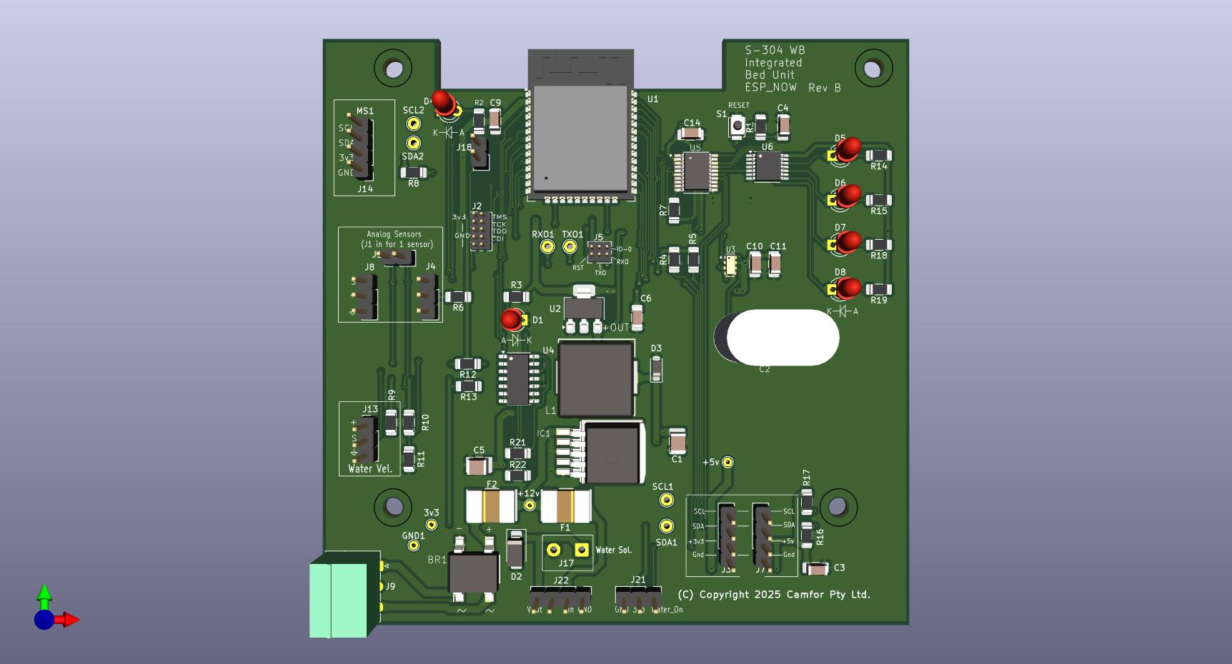
Attached is a pic of my PCB and the I2C pins are at the top, left side.
Firstly, I want to know which devices you got. Do they have internal pull ups already?
Second, let’s run a test.
If you shorten the length of i2c cables but attach more than 2 devices, do you get success?
If so we know the length is a contributing factor.
At a basic level, the two lines need to be pulled up with the pull up resistors. The actual value of these can take a bit of work to work out the best values for the setup/out you need.
e.g. High Value pull-ups (weak pull ups) have less current flowing thus long for the bus to “recharge” (adding distance and more devices also add to slow rise times).
So putting in lower value (weaker) pull ups and supply more power faster allowing to faster re-charge time on the bus.
BUT you dont wont the values to be to low/weak as that will mean the I2C chips need to dispute more power to pull down the bus for the comms.
So as per @Pixmusix comment re do the devices have pulls, this will have the effect of having stronger (lower resistance) pull ups as the device talking now needs to pull down the power for ALL the pull-ups.
Slower speeds may also help, ie. giving more time for the bus to charge and hold.
I’m no electronics engineer, so my comments may not be relevant … however…
I use quite a few i2c devices, and 5 is definitely not the limit More likely the distance of your cables, since i2c was designed for short distances (like, between ICs on a circuit board). Do you have several i2c devices at one location which is 1m from the microcontroller - or is each device a metre away along a different cable ?
The issue is not the length of each cable - but the total length of all cables in the i2c bus added together.
Also, I note 3 connectors on your board are labelled with SCL and SDA - are these all connected to the same SCL & SDA GPIO pins on the ESP32 ? It is possible that they are separate i2c buses (connected to different sets of ESP32 GPIO pins).
Another alternative I came across for i2c over ethernet cables is SparkFun QwiicBus - both EndPoint and MidPoint devices. Much more expensive, so I hope my length won’t need it.
I notice also that Core have a couple of i2c signal isolators. I doubt that these would have an effect on the distance, but might be useful if you are getting interference on the wires.
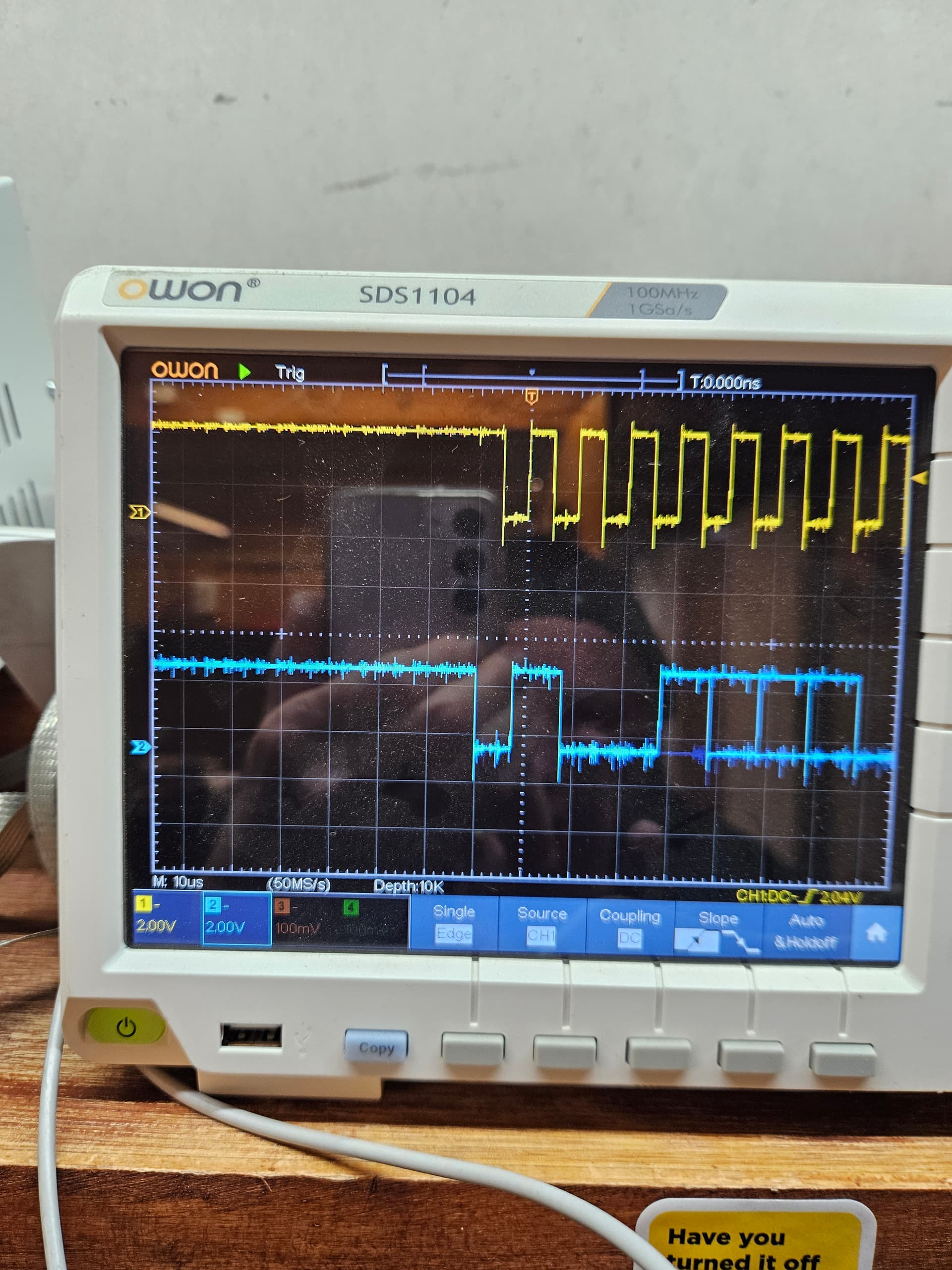
I can’t seem to narrow this down. First up, I reduced the cable lenghts (as suggested). It made is slightly better as below. This is with only 2 Adafruit moisture sensors.
100khz should be fine. You could slow that down and it might help.
The clock signal looks fine. Ringing a bit, but whatever, we’re not measuring gravitational waves or synchronizing critical infrastructure so I would call it artistic license and move on.
Maaaaybe a capacitor to smooth out the data signal… I’m talking 10nf absolute max. I think those messy transitions at the end of the data-word could be solved with some aggressive pull-ups. Start with 3k and work you’re way down.. I guess. That’s what I would do.
What I noticed was that, if I reduce the cable length of the ribbon cable between my I2C backplane and the ESP32 PCB to only about 20mm, I can reliably add a 3rd Adafruit sensor (also with the reduced cable length). This all seem to suggest capacitance is the issue.
the bit that really stands out to me is the scope image where it does not work, seems to have a higher speed clock dumped onto the wire. (may check just that 3rd unit by it self)
I2C should be held high with no comms, so the High level comes from the pull up resistors.
The low level comes from one of the nodes sinking the power to ground; i.e. pulling it down.
So to see such a big swing seems to hint something else is dumping a clock/wave onto the line.
Hi Gerard
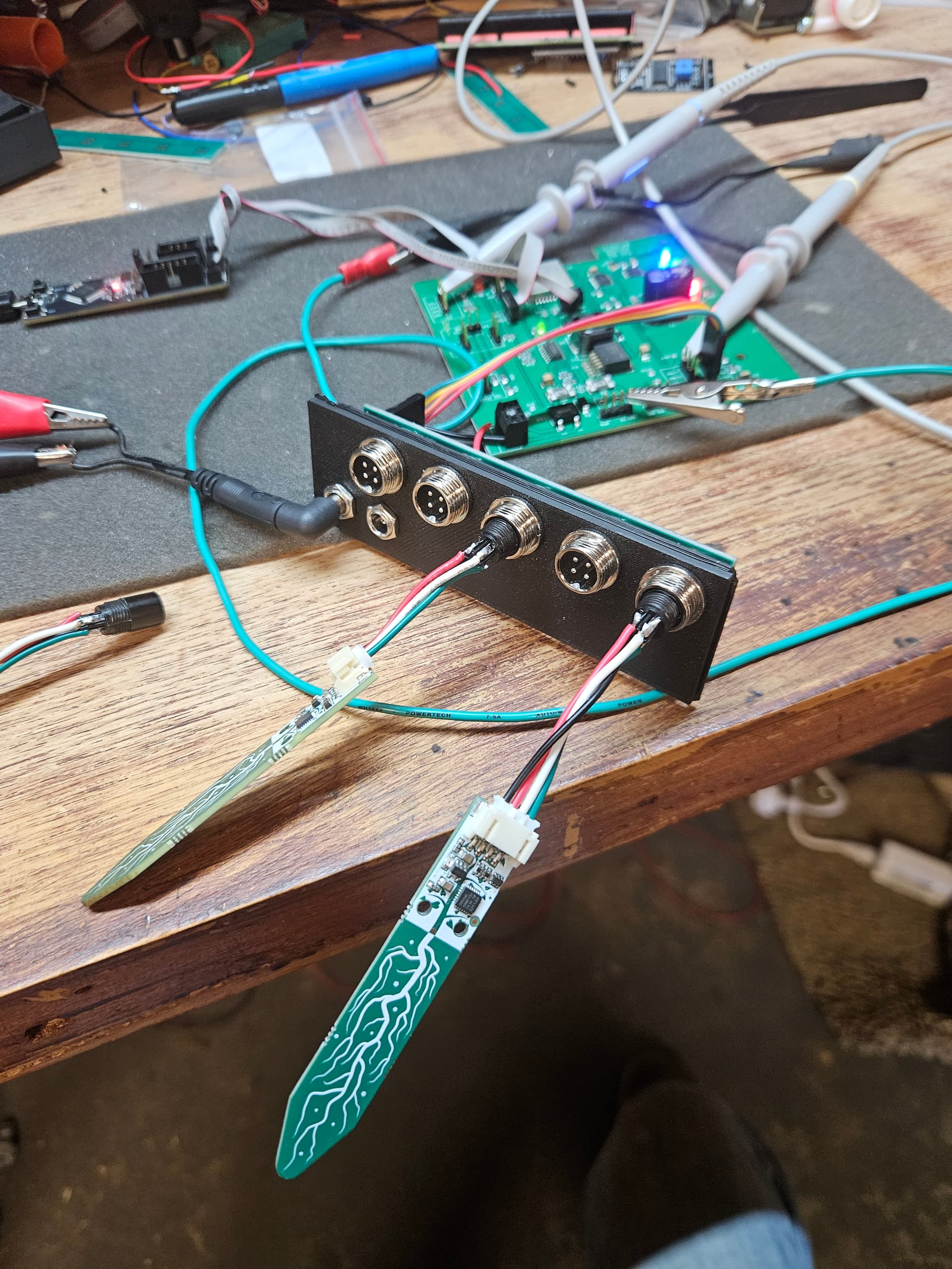
It is a bit unclear in the pics but how long are the oscilloscope probe earth connections. It looks like at least one of them connects to that green wire laying all over the table. These should be as short as practicable and connect to ground points as near as possible to the measuring points. It is quite probable that all that crap you see on the oscilloscope is being put there by measuring techniques. Also the probes (and oscilloscope inputs) should be set to the X10 position and properly adjusted using the oscilloscope built in square wave signal.
Cheers Bob
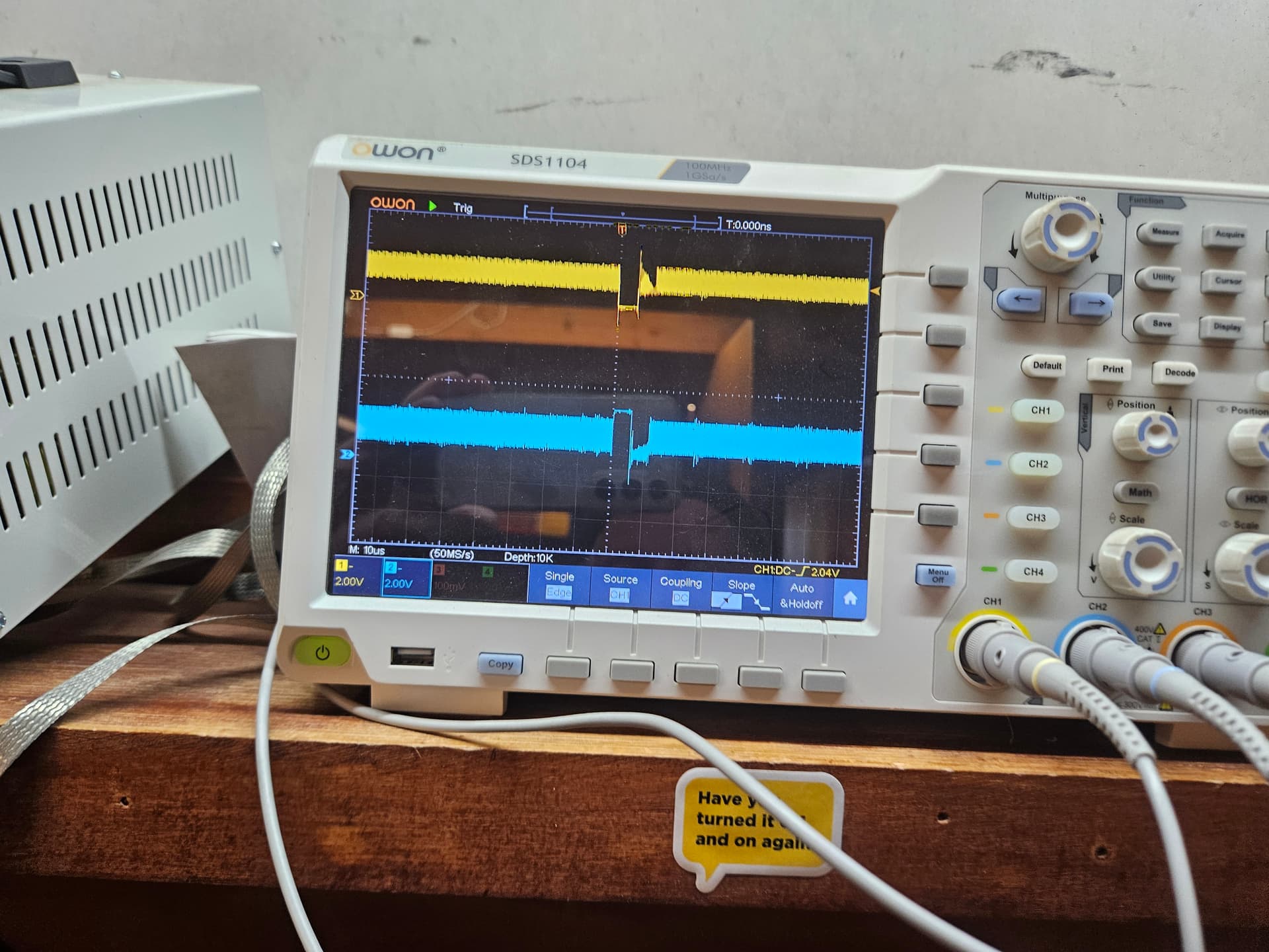
I’m beginning to think this is a weird RF problem. Reason is that, when it goes bad, there’s a signal of about 65Mhz on the line and that is even with the ESP32 RESET button pressed. I can even hear it through the FM radio.
Also, the I2C bus scanner code can be running quite happily but putting a scope probe onto the SDA pin sends it bad. This should not happen.
Something may be acting like an antenna(?). RF is not my strong suit.
Yeah, it looks a bit aggressive. Is there enough power getting to the “3rd” board ? Im wondering if the sensor ic is rebooting due to brownout, as part of that roboot is pulling down the I2C lines, then once booted, puts the pins into a HiZ state, allowing the pull ups to bring it back up and repeat.
So while its happening, probe around the remote boards as well as the main one to see if you can find the issue.
Hi Gerard
There is an old story about a camel’s back and a straw. Could apply here. 2 sensors could put your supply to the limit and it won’t handle 3.
Cheers Bob
Also make sure you don’t have too many pull ups. This can be a drain on supply current.
I think in theory you only need 1 pair, 1 on SCL and 1 on SDA. for the whole string.
The “fun” part here is the resultant pull up power needs to be able to be pulled down.
e.g. The Raspberry Pi Pico’s RP2040 microcontroller GPIO pins can sink a maximum of 50mA of current, but individual pins are limited to 12mA
So in this case, if it was a Pico with 12mA max sink current, then the pull up resistors (total) on a line need to allow less then that amount of current.
So (lets see how my math goes)
V / I = R
3.3 / 0.012 = R (change units to Volts and Amps)
R = 275 ohms (so total resistance of all pull ups need to be this or bigger (for 3.3V and max 12mA sink current)
Hi Michael
All very true but be aware you are pushing everything to the limit.
So with that theory, given the maximum sink is 50mA the maximum number of pull ups @ 12mA would be 4. And absolutely nothing else that requires sink current can be connected.
Not a good scenario. If it were me (not likely as I am a big fan of a few more volts) I would stick to about 10kΩ as a general pull up value. I think that being a voltage operated system if a much lower value of pull up is needed i would start looking at WHY this is so. If it is to swamp out interference start by looking at wiring techniques etc. In particular the rats nest of wires that is evident sometimes. Also the breadboard. Recently I was playing with a 555 timer and had some errors. I found the device worked quite happily with no timing capacitor fitted. By measuring this free running frequency I estimated the stray C (which became the timing cap) to be some 50pF. And that is just between pin 2 and Gnd (Pin 1) and there will be all these little stray caps everywhere, not to mention any stray L that will be there.
Cheers Bob