
Good point with the current limiting. I’ll check it.
Hi Gerard
Please let us know what you find. Helps with eliminating possible causes.
Cheers Bob
This is a bit of a needle in a haystack.
I have it working reliably with (believe it or not) with 4 x Adafruits, 1 x HDC302x ambient temp sensor, and an on-board RTC. 6 devices.
I also moved the pullups gradually to 5k6. Haven’t gone higher.
I’m using platform.io as the testing software so as I can adjust the clock. Arduino IDE doesn’t do that.
The cross talk is remarkable….
This is at a 10khz clocking rate….
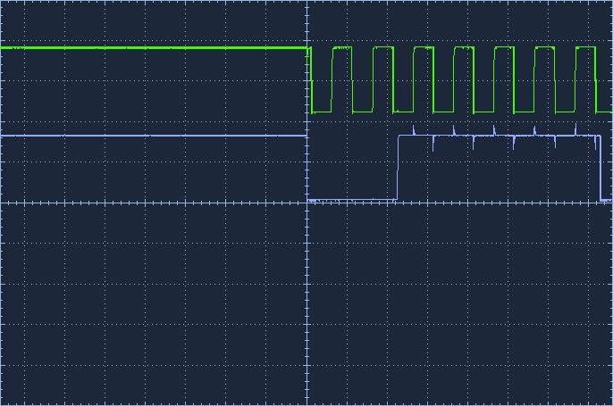
Unfortunately, the Owon scope does not include the vertical/horizontal settings. The horizontal is 100us/div.
This is at 400khz….
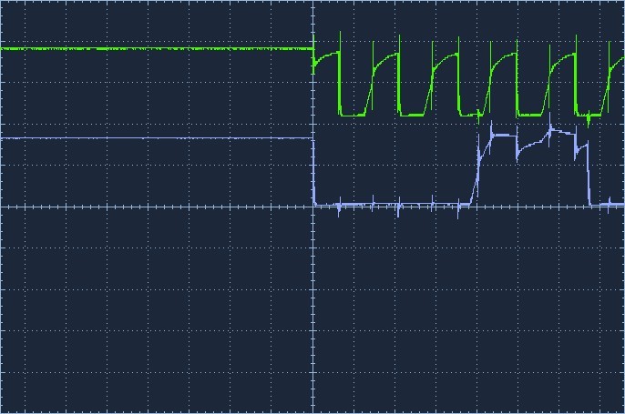
The timebase here is 2us
Expanding out to see the spikes.,….
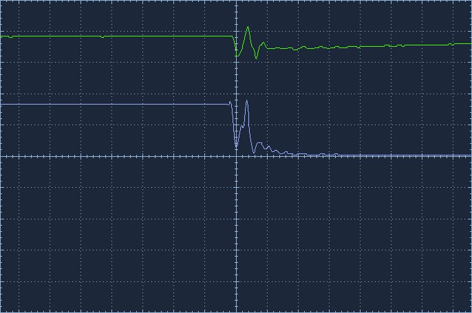
These are 25ns spikes
Even at 400khz, the I2C scanner works quite reliably.
Progress, working is good.
As per bobs comment (many times) some of the spikes you see on the scope may be due to the scope probes ground connection either missing or not as close to the test point as it should be. the higher the frequency the more important that is to get the best test results.
Gerard
Good result. What did you do, increase the 12V current limit ?? If you don’t let us know no one will know what was wrong in the first place. I did ask you to advise on that current limit check. If you are not going to tell everybody what you are doing to get the result you have nobody will know if their diagnosis was correct or not. You have at least advised us of your scope settings so now the pics mean something.
I have said it before but will repeat, getting information is sometimes like pulling teeth.
Cheers Bob
That is good, but does your set up with the sensors connected work at that frequency.
Hi Michael
Would nearly put money on that. I think some of the measuring techniques are in need of a brush up.
Cheers Bob
Might be worth employing some probe ground springs. You can make one easily enough from a scrap piece of wire if you don’t have any… then you can put scope probe ground within a few millimeters from the tip…
Cheers,
T
Hi Trevor, Gerard, Michael
Upper market probes used to come with a little device in the extra bits bag. It is a circular sleeve with a spring or connection arrangement. You remove the part of the probe with the hook in by mostly simply pulling it off. That leaves a small spike from the centre of the body and a metal sleeve (usually gold plated) around the probe body just behind the little spike. The circular ring part of the springy connector bit then slips over (a firm fit but not overly tight) this sleeve which gives you a very short probe ground connection.
The down side of this is you lose the probe hook and you have to hold the spike onto the measuring point.
But you can’t have everything too easy.
Individual probes could be a bit different but that is the general idea. Look in the extra bits hat came with the probe and you might find this. You may not have known what it was and discarded it or if an el cheapo probe this little item might not have been supplied.
Cheers Bob
Hi All
This is the sort of thing I mean.

The “Ground spring” on the right hand side is what I refer to.
This from an Element 14 page and is part of the data sheet of a $600 500MHz Pico probe
Cheers Bob
Yep… and here’s the one I made the other day… out of the wire from a “bag-tie” thing… stripped of the plastic, wrapped the wire around a drill bit to make the coil… and fitted it over my probe tip. Worked just fine 
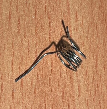
Sure, proper spring steel would be nice…but I wanted it TODAY, not in a week!
If you are not sure how it goes on your probe… simple… like this:

Just make sure you wind the coil a bit smaller than your probe diameter, so it makes a good tight fit. Otherwise, it sort of defeats the purpose…
Cheer, T.
Hi Gerard
Not really, there is usually a reason for everything
You don’t say whether your scope probe is connected or not when you do your I2C scan.
But it is very probable that all or most of these “crosstalk” spikes disappear when you remove the probes so everything works.
Cheers Bob
Hi Trevor.
That’s it…
Tektronix, HP, and other up market manufacturers used to (and probably still do) supply these with the probes. Unfortunately I haven’t had that (read can’t afford that) luxury for a lot of years now.
Cheers Bob
Yes, I do have spring clips.
1 Like
Yes, the probes were attached. Actually, removing the probes makes it fail.
To make the schematic simpler, I removed pins 6, 7 from the level shifter. 6&7 are the 3v3 side of the device.

Doing this has fixed it.
1 Like
I’ve been fixing things from mainframes to toasters for 50+ years! I’ve a fair idea about troubleshooting! One thing I’ve learnt to do over the years is consult widely with challenging issues like this as no-one has all the good ideas.
1 Like
Hi Gerard
Does that mean the whole thing is OK now ??
If not a clue might be here
Attaching the probe effectively connects your “Ground” to mains earth, ie; actual “Ground”. I believe what is referred to as “Ground” on the schematics is the negative side of the power supplies.
Why this would have any effect I don’t know and I think would be pretty hard to pin down.
For what it is worth I mostly use my scope with the mains earth disconnected. I have about 30cm of extension with the earth wire not connected but hanging out of the plug and socket so it is very obvious. Habit form situations where there is 2 earths, mains and technical. Using the mains earth for instruments can actually introduce hum into a system in this situation. There can be quite a few volts between the 2.
Down side to this is you have to be aware the scope chassis is floating and you don’t connect probe earth clips to 2 different bits of equipment unless they have a common ground point.
Cheers Bob
1 Like
It LOOKS pretty solid. I have modified 10 so far and they all work.
You can see where I hacked the pins on the TXS0108. The reason I did that was to try to make the whole thing more simple following on with the weird situation where the scope probes were affecting the signalling so very much. Removing these pins would remove the I2C @ 5v completely may have provided more clues (crosstalk, antennas, etc). Instead the whole thing started working 100%.

Below is how the external devices attach.

The whole rationale behind having a kind of “backplane” is to reduce mfg costs.
I think @Michael99645 and yourself mulled about whether the TXS was having a deleterious effect or not. To test this, I grabbed another sample PCB and cut the pins on the 5v side of the TXS thus leaving the 3v3 side connected to the rest of the circuit intact. Result: still failed. So that points to the TXS device itself rather than some weird crosstalk issue with PCB traces, etc.
I’ll post up a screenshot of the scope shortly.
2 Likes

1 Like
So you think something to do with the level converter is/was the issue ?
Edit:
This is interesting from theTXS0108 data sheet
Each A-port I/O has a pull-up resistor (RPUA) to VCCA and each B-port I/O has a pull-up resistor (RPUB) to VCCB.
RPUA and RPUB have a value of 40kΩ when the output is driving low.
RPUA and RPUB have a value of 4kΩ when the output is driving high.
RPUA and RPUB are disabled when OE = Low.
2 Likes
@Michael99645 Yes, I do. I think you were on the money here by raising the possibility. I did research this after you mentioned it and everything I read suggested that it should be OK!
1 Like