This is a placeholder topic for “Logic Level Converter Bi-Directional” comments.
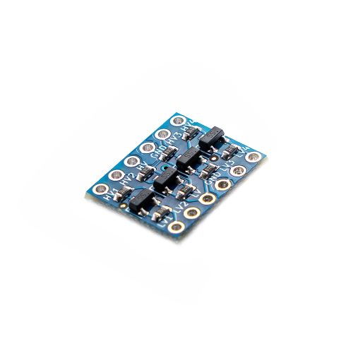
This Bi-Directional Logic Level Converter is a breadboard-friendly device that converts between 5V and 3.3V logic.
Read moreThis is a placeholder topic for “Logic Level Converter Bi-Directional” comments.
This Bi-Directional Logic Level Converter is a breadboard-friendly device that converts between 5V and 3.3V logic.
Read moreI need to connect a 5V I2C device and a 3.3V I2C device to my 3.3VRpi. Can I use this level converter device? How would you connect it up?
Hi Steven
Sparkfun have a good guide, I’d recommend checking that out! Bi-Directional Logic Level Converter Hookup Guide - learn.sparkfun.com
Hi Steven
If you read the description on the Core product page you will find the following.
“Power the board from the two voltage sources you’re using. Connect the higher voltage (eg. 5V) to the ‘HV’ power pin, the lower voltage (eg. 3.3V) to the ‘LV’ power pin, and the ground to the ‘GND’ pin.”
That just about sums it up.
The link Liam has provided goes into this in more detail.
Cheers Bob
Many thanks. I subsequently found another article which also helps:
Hi Steven,
Using a logic level converter to compensate for the operating voltages of your sensors is a clever solution and should work but I think connecting two master devices like a Raspberry Pi and an Arduino Uno to the same bus is a little bit more complex.
To have two master devices on the one bus both need to be setup for multimaster I2C, from the reading I’ve done that should be possible with the hardware of Pis and Unos, but you may need certain libraries or drivers to make sure it’s operating well.
Here’s a poor-man’s version of a level converter if you aren’t able to source a CE07510 or you are doing a quick prototype and one isn’t available. You can convert between 5V and 3.3V.
Since the logic high and low thresholds are specifically defined for IIC, and devices only pull low, it doesn’t matter what voltage the bus devices are running at as long as they can handle the pullup voltage. It is perfectly OK to passively pull up the lines to 3.3V, then mix 3.3V and 5V devices on the bus .

The Schottky diode is there to reduce the capacitance of the Zener diode, which typically has a higher capacitance in comparison. The Schottky should also help to minimise the zener noise on the data lines too, which can cause transmission errors. The combined capacitance is given as C = 1/(1/C(zener) + 1/C(Schottky)). Typically, I have found the combined capacitance to be around 100pF at most, depending on the diodes used.
Depending on the 5V and 3.3V devices, you may have to play with the resistance values. Using a 120 ohm resistor can be used in high bandwidth situations (can handle up to 20 MHz), but this is typically close to using, for example, a Raspberry Pi’s 16mA GPIO maximum allowed current. On the flipside, using a 1 kohm resistor will use much less current (about 2 mA), but its 2RC value is much longer (around 200 ns), so if your switching frequency is >2 MHz, this is likely to cause transmission errors.
Given I2C requires 2 wires, namely the SCL clock signal and the SDA data line, the above circuit needs to be duplicated for each wire. The grounds for the two devices must be common too. This type of circuit should also work with logic-level USART and I2S, although the increase in wires and the required multiplication of the circuit become a pain and a level-shifter like the CE07510 becomes much more attractive. Note that the circuit is also unlikely to work with CANbus-style protocols that require signals to reach full line voltage and half voltage (recessive).
The Ground connection …
By looking at the circuit diagram and the PCB layout ( I’m getting better at KiCAD ![]() ) it appears that the Ground connection is not actually connected to anything.
) it appears that the Ground connection is not actually connected to anything.
I can see that the bottom of the PCB has an almost full ground plane coverage - do I ‘assume’ that a ground is useful as a generic reference layer or as a ‘shield’
Hi Murray
Yes the schematic for that device can be a bit misleading as the ground is not shown at all. It would be in fact connected through and yes it should be connected to each device even if only to make sure the grounds of the 2 devices are connected. The grounds are shown on the pin out diagram.
Cheers Bob
All good - the grounds are actually all connected elsewhere on a large ground rail, but I will drop a ground wire over to the level converter also to be sure to be sure
Hi Murray,
Also worth noting popping ground leads across different parts can become problematic in some instances (usually when dealing with high power and/or sensitive analog inputs).
Some rules I use:
Strictly speaking, it is shown, because there are two labels that match and therefore the conclusion must be that they are connected. This is an old standard, but modern practice carries it to extremes, using matched labels when a connecting line would be simple to draw and much more obvious. This makes the schematics more difficult to trace than they need be, and can be extremely confusing, particularly when you are trying to find all connections for a particular trace. The practice seems to be becoming widespread. I can see no reason for laying that schematic out the way it appears other than to avoid having the HV and LV connections crossing over some others. To my mind that is much less of a problem than having to track labels from place to place and make the inference about matching labels referring to the same connection. There is no reason to break down such a simple circuit into 5 separate parts.
Hi Jeff
I could not agree more. It is so easy to miss a connection when trying to work out just how a circuit might work. All well and good when a computer connects them all up as a netlist but it does not help if all you want is to look at it. You finish up with a page full of labels which may or may not mean anything as they sometimes speak a language all of their own.
Exponents of this system please note. If you continue going down this path consider adding a number to the Heiroglyphics you call a description to indicate how many connections there are to this point. So for instance if the number “6” is appended to a particular connection and you have only accounted for “5” then you have obviously missed one. This however requires ACCURACY so you are not looking for non existent connections. Maybe the word “ACCURACY” might frighten some people off as this trait seem lacking on some occasions. Far easier to let the end user muddle their way through.
Cheers Bob
I need a level converter solution for a very compact WS2812 wearable controller I’m building. As I only need to level convert a single data line, would it be possible to desolder one SOT23 chip and use it? While this product is quite small as it is, I’d ideally like my built to be as compact as possible. Or are there other compact single level converters available?
Hi Rob
You will also need the 2 pull up resistors.
Cheers Bob
Thanks Bob,
That is easy enough
And thanks for the quick reply
Hi Rob,
If you need something to mount those 3 chips on, you could cut off a bit of one of our SMT protoboards, it has spacing designed for medium-sized SMT components like SOT23s.
But otherwise it looks like you’ve got this all worked out ![]()
-James
I see it mentioned of just HV, can it handle a 12v to 3.3v shift ?
Don’t see why not.
Cheers Bob
Hi there
Are you going to be stocking the new Pimoroni PGA2350 with the RP2350B?
If so, any idea of when you might have stock?
Thanks very much.
Cheers MG
And you can get our latest projects and tips straight away by following us on:
![]()
![]()
![]()
![]()