Hi fellow makers! I’m 90% done with my project of making true wireless stereo desktop speakers. They sound amazing with good sound stage reproduction! I love that I can take them anywhere and place them just the right distance apart, and from me, to listen to songs with great sound stage effect.
I used Creative Gigaworks T20 speakers because they have separate tweeter and cone speakers. I run them with a small 30w amplifier board (12v power input from a 3S 18650 pack) and the music input comes from a pair of cheap clone AirPod earbuds.
The problem I’m battling with now is I want to use a DC step down module (12v down to 4v) to power the earbuds but after trying 2 different step down modules, the earbuds don’t seem to do well with the power coming from it.
They either keep turning on and off, and if they stay on, there are constant interference sounds audible from the speakers.
If I power them from a LiPo battery then they work just fine and the speakers sound fantastic.
Any advice on how I can power the earbuds from my 12v battery pack so I don’t need to have a separate battery for the earbuds?
A super quick but nasty fix could be to put a capacitor across the inputs or using a voltage divider (since the batteries voltage will drop this might not be an option, mapping the batteries discharge range onto a working voltage for the earbuds).
There are definitely more considerations here that I’m not sure of but hopefully this gets you pointed in the right direction!
I’m not 100% certain what is causing the interference in the audio you are experiencing but I have two ideas of what it might be that could be worth investigating.
What Liam suggested! He just beat me to post. Switchmode regulators make tonnes of electrical noise, often around the 20kHz frequency range.
Since you have two separate power supplies there may be a grounding issue where one supply is ‘floating’ relative to the other. Are all your grounds tied back to a single point?
Hi Liam!
I have tried out these 2 step down modules purchased from Aliexpress.
The LM2596 one has capacitors built in and still the same result, noisy buzzing and beeping audible from the speakers.
Yes, I’m beginning to understand what electrical noise is now with this issue.
The problem exists when I use only 1 power supply, a 3S 18650 battery pack, and then I step the 12v down from it to 4v to power the earbuds.
However, when I power the earbuds with their own separate 1S battery, they work fine and there is no electrical noise emitted from the speakers.
My goal is to be able to power the whole build from just the 3S battery pack, failing which I will have to install a separate battery, charging board and switch for just the earbud in each speaker.
I see, it seems like your switchmode regulator is the culprit then. There are two ways you could be getting noise into your circuits either through the power supply voltage rails, or induced in the board as RF interference.
To fix up your power supply rails you could add some filter capacitors to block the high frequency transients on the line as Liam suggested.
To protect against induced RF noise you could try and shield your regulator with a metallic enclosure. Effectively a Faraday cage to catch the stray signals. Just be super careful not to short anything out and connect the enclosure only to the ground rail.
Hi all
This is one time where it would help to actually hear this noise as this can sometimes offer a clue as to the origins.
It seems to point to power supply switching but it does not have to be on the power rails. It could be radiated into the earbuds as RF. I am assuming they are the radio receiver devices. Similar to the interference caused by 240V LEDs and AM radio reception. I have such LED down lights in Kitchen, Dining and Lounge room and AM reception is almost impossible with the lights on.
Something to try. Physically separate the switching converter and earbuds as far apart as possible. At least 2 or 3 metres to prove the possibility. Access to an oscilloscope would also be very useful to see exactly what this “buzzing” looks like and possibly get some clues.
If this interference is radiated as RF into the earbuds or indeed the amplifier input all the capacitors in the world across the power supply will not help. The only way to fix this is shielding. Put the down converter in a metal box and connect that to the common ground of the system. If This radiation proves to be the problem ideally the wires entering and exiting the box should do so via feed through capacitors or passing through a ferrite bead may help.
Cheers Bob
Hi guys, just wanted to update and bring closure to this thread. The solution was to just not bother with powering the earbud with 5v step down power and try to eliminate the noise.
I’m now powering the earbud with a Li-Ion battery and the 5v step down power is connected to the charging circuit of the earbud in order to charge the Li-Ion battery.
The earbuds turn on automatically when the charging voltage is turned off, so that is the perfect way to get them to turn on, with a switch for the charging voltage.
Hi Jacques
Thank you very much for that. Simple solutions are often the best. With your problem the alternatives could get a bit messy.
Once again thanks for letting the forum know the outcome. Too often a problem is left in limbo and no one is quite sure whether advice or help has solved anything. No one learns anything that way.
Cheers Bob
Great to hear you had success in the end, and thanks for closing the loop on the thread. As Bob said so many threads end with a mystery and leave you wondering if the question was ever answered.
Good luck with the next project!
Oh no, I jumped the gun. I finally got everything soldered and wired up and guess what, there is still interference!
Now I’m even more confused. How is it that even when the 5v step down converter is not receiving any power, it can still generate interference as long as it is connected to the earbud?
Once I unplug the step down converter from the charging circuit of the earbud, everything works fine. So simply cutting power to it is still not enough. There is something else going on that I don’t understand.
So am I. (and maybe others too). I thought you got rid of that converter. If it’s not doing anything why is it still connected to anything. If the converter is your trouble, which on what you indicated previously seems to be the case, it could somehow be powered and as suggested before radiating the interference.
Without knowing exactly what you have got and how it is all connected I for one would only be guessing.
This is the way they would normally work isn’t it? I don’t know as I am not familiar with these earbuds. How are they powered in normal use? If they are chargeable I would imagine you would plug in a charger then remove that to use the earbuds.
Any chance of a circuit so we can see what you have done. It would be a big help to stop going in circles.
Cheers Bob
I used a set of QCY T1 wireless earbuds. The case has a battery in it that supplies 5v to charge the earbuds when they are placed into the case. When the earbuds are removed from the case, they automatically turn on.
Hence my attempt to replicate that process of charging the 14500 Li-Ion battery used to power the earbud by connecting stepped down 5v to the charging circuit of the earbud. When the push button switch cuts power to the step down converter, the earbud automatically turns on but interference is present.
You can hear what the interference sounds like here. Click on the Download Audio link near the bottom of the page to load the sound file player in your browser. https://sndup.net/96x7
Hi Jacques
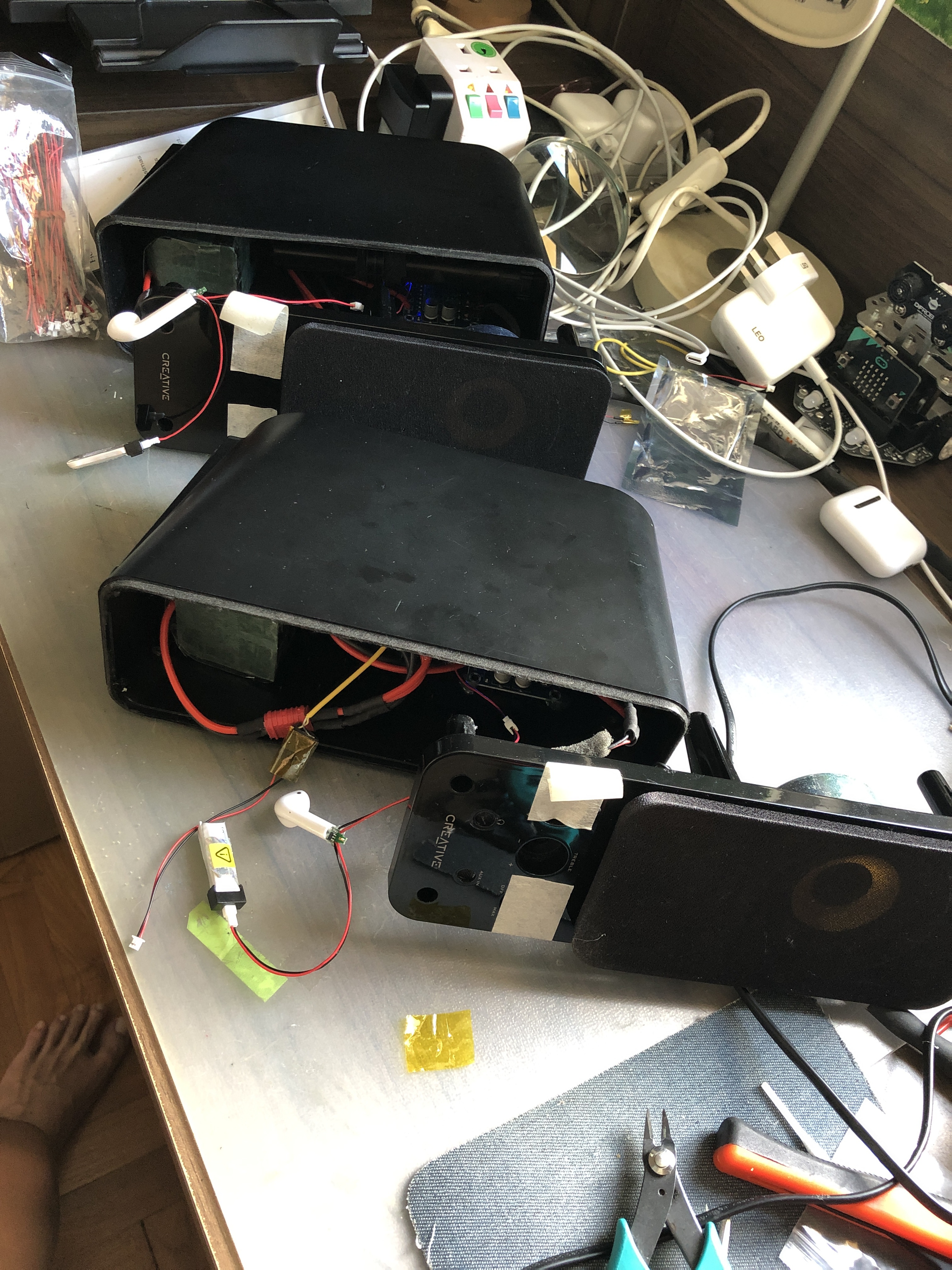
Could we have a bit more detail re connections to that board at upper left pls. I assume that is the earbud.
What is that gizmo hanging off the connection bottom left of that board. Looks like an electret microphone or is it the earbud speaker.
Your 12V to 5V converter does not agree with any units in that link you provided. More info pls.
That noise is interesting. Sounds like a mixture of hash and feedback although the feedback (if that’s what it is) is not there all the time. Could be a bit of 50Hz rumble in the background too. If that is the case this component is most certainly mains pick up from the surrounding environment or an eathing problem.
I will try to have a look at this on my oscilloscope if I can, but maybe not today.
Cheers Bob
Hi Bob, I’ve updated the schematic with more detailed explanation. Please see post above.
Yes, the gizmo is the microphone for the earbud.
Regarding your comment “12V to 5V converter does not agree with any units in that link you provided”.
The earbud takes 5v input to charge the battery that powers it. I call it the “charging circuit”.
So, the earbud is being powered by the 14500 Li-Ion battery and 5v converter is connected to charge the battery. This charging normally happens when you place the earbud in its case.
The image of your converter does not agree with any of the converter images in your link. I was just trying to get some info re what you are using.
What is the microphone for? In your application you would have no use for it have you. If no use get rid of it. Possibly causing feedback.
The connections to the earbud board are not very clear. It looks like the converter and microphone are connected to the same point which does not sound right. Also the battery and wires going to the class D amp seem to be connected together which is very confusing. You have black to red and red to black which does not make sense either. There seems to be something wrong here so much more detail in this area would be good or essential.
Cheers Bob
I removed the microphone and the interference is still there.
Sorry, I didn’t bother to be accurate with the wiring in the diagram because they are correctly wired.
Without the 5v step down plugged into the charging circuit, the speakers work and play music just fine in true wireless stereo mode.
That would be the most stupid statement I have ever seen. If you are so confidant how come you cannot solve your problem.
I can see straight away what could be a serious problem. The converter input and output are reversed and you have nothing connected to the “enable” point. Also have you made any of he links on the back of the board. should have at least one, either a fixed voltage (in your case 5V) or variable (trim pot adjustable).
If you do not see fit to provide connection details I don’t feel there is any thing more I can contribute. If you say everything is correctly wired and I see that the connections to the converter reversed I don’t have too much confidence in the rest.
Cheers and good luck Bob
Bob, thanks for your time trying to help me. I’m greatly appreciative of it.
I have now used 3 different step down converters (you can see the other 2 in my post above). All 3 converters produce the same kind of interference which you heard already in my attached sound file. I use a multimeter and adjust the potentiometer on them to get exactly 5v output.
And for the most recent converter, I bridged the ADJ link on the back so that I can use the potentiometer to adjust exact output voltage.