MCP266 CanOpen

Using Basic Micro Motion Studio to configure a MCP266 Motor drive, need to be able to communicate with it via Can open, running a script from the terminal is no issue how ever i cant read or write anything to the bus.

any help would be greatly appreciated.

Hey @James_F,

Welcome to the forum!

Sounds like a tricky setup! Could you please share some pictures or screenshots of your configuration, wiring, and the terminal output? That would really help us understand what’s going on and offer better advice. Thanks!

Appreciate the Reply and apologies for mess ive got going on in those photos.

CAN is connected pins 5-12

im assuming i need a 5+ supply, this is connected pin 3 with GND on pins 2 and 10

im using basic micro motion studio to write to these devices, attached is a photo of the settings, 250kbps is what the rest of the bus is running,ive allowed nodes 100,110 and 120 for these 3 devices

im not real familiar with the MCL files but from what i understand from the user manual i should be able to read 4 Bytes from the Can bus and print to the terminal with;

value var long

main

gets 1,[value.byte3, value.byte2, value.byte1, value.byte0]

puts 0,[dec value,13]

end

this only returns 0.0.0.0

running the device with the power command works, its just interfacing with the CanBus that im struggling with

1 Like

Hi James,

Welcome to the forum!! Sweet setup :smiley:

To confirm, is this via CAN or some other protocol?

From my FYP we had an SOP specifically for debugging the CAN network on the project.

Out of curiosity what CAN adapter are you using to communicate to the module with?

Liam

Good Afternoon Liam

Yes, CanOpen

the Modules are being run from an IFM CR1140 PLC, using IFMs CanFox im able to look at the Canbus message stream

Im communicating with the module via a USB cable to my laptop

1 Like

Hi James,

If you measure the resistance across the CAN H and L lines can you see that it is terminated correctly? (Approx 60-ohms)

To confirm, when you mention that you can communicate to the module through terminal, is this via the CAN connection?

Would it be possible to send through a screenshot of the messages you are receiving?

Liam

Good afternoon Liam

Resistance across the can reads 59.8-ohms

Terminal script is as follows, this is just running a motor for testing purposes, this works fine

connected via the USB cable on the left, not the CAN connection

Attached photo of the CAN Stream via IFM Maintenace

70A and 71E are sync messages from other devices

CEA0003 and C000003 are Outgoing messages for a J1939 system

628,632,63C,646,650 and 65A are outgoing messages to Linak actuators

and the last 5 messages are incoming from a battery monitoring system

2 Likes

Just to add some context to this one, the motor controller in question is MCP266 Dual 60A, 60VDC Advanced Motor Controller

The manual for this particular one can be found here:

I have let our team know about this one. A team member with more knowledge in this area should be able to offer some useful advice!

2 Likes

Hi James,

I found a couple of excerpts from the manual and datasheet.

When USB is plugged in the module you are connected to will be configured as the master (no heartbeats unless programmed to)

The actual DBC structure of that node uses the DS402 profile: https://webhelp.kollmorgen.com/studio/Content/Kollmorgen%20Studio/3%201%202%20Drive%20States.htm

The program and config you had before doesn’t seem to be setting up all of the requirements for CAN according to GPT.
And since the wiring is correct, hopefully this just works!

Here’s a complete MCL-Basic script that will:

β€’ send the CANopen β€œStart Remote Node” to node 100
β€’ then loop, reading PDO1 (4 bytes) from that node and printing the 32-bit value to UART0

—––––––––––––––––––––––––––––––––––––––––––––––––
Before you load the script, in the Studio GUI under β€œCANopen” β†’ β€œMailboxes” configure:
β€’ Mailbox 0: Direction=Tx, COB-ID=0x000, Length=2
β€’ Mailbox 1: Direction=Rx, COB-ID=0x180 + 100 = 0x1E4, Length=4

Make sure CAN baud=250 kbps, Node-ID=100, proper termination & 5 V/CAN GND wiring as discussed.
—––––––––––––––––––––––––––––––––––––––––––––––––
value var long      β€˜ 32-bit container for the 4-byte PDO

main
β€˜β€” send NMT β€œStart Remote Node” (command=2) to Node-ID=100 β€”
tx 0, [ 2, 100 ]     β€˜ mailbox 0 is your NMT TX box (COB-ID=0x000, len=2)
delay 100            β€˜ give the node time to enter Operational

β€˜β€” now loop & read PDO1 out of mailbox 1 β€”
while TRUE
if ( gets( 1,    β€˜ mailbox 1 = Rx mailbox for COB-ID=0x1E4
[ value.byte3,
value.byte2,
value.byte1,
value.byte0 ] ) == 0 ) then
β€˜ on a successful read, print the 32-bit value in decimal
puts 0, [ "Node100 PDO1 = ", dec(value), 13 ]
endif
delay 200          β€˜ poll every 200 ms
wend

end
—––––––––––––––––––––––––––––––––––––––––––––––––

Liam

2 Likes

Thank you for the reply, Liam

I’ll look at the Can Open DS402 profile link you’ve provided over the coming days.

I can’t seem to find the 'β€œMailboxes” section as mentioned in your last message. am I possibly using an outdated version of motion studio?

Yesterday I’ve managed to get the module to Output 0x764 00 as a boot message (0x700+CobID, 00 in BYTE 0)

Thank you for the provided script, however it seems to get stuck on line 11 for some reason, ill look into this more over the coming days.

appreciate the effort you have put into this issue already :slight_smile:

2 Likes

Good evening All

Just thought id provide an update on this issue.

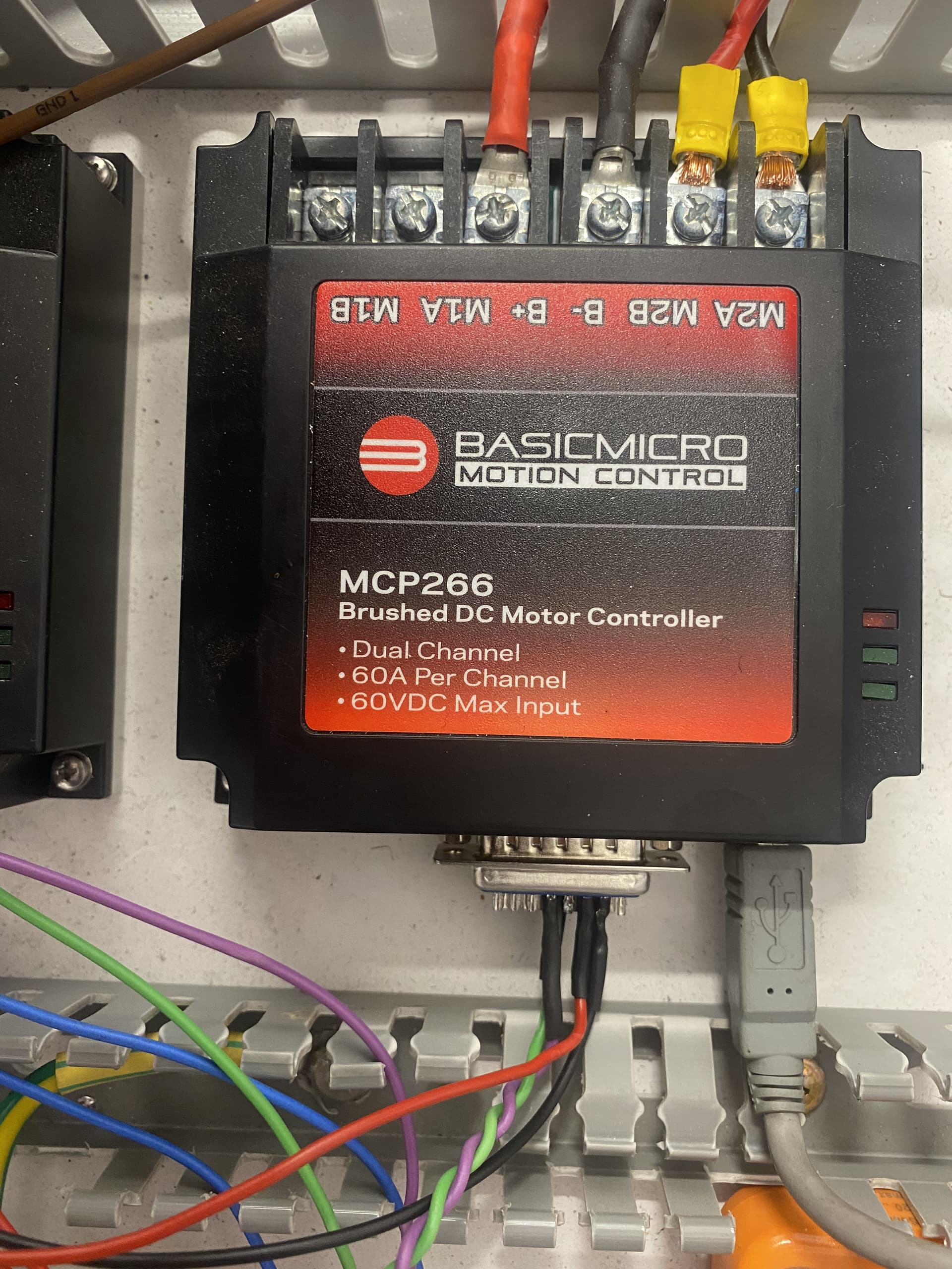
Following on from the last message from Liam, i contacted Basic micro in the US, Nathan provided me with an updated β€˜pre-release’ Motion Studio with updated firmware also.

This new Motion Studio has a much more indepth CanOpen setup, however i was advised that for what i need the MCP266 to do, MCL Can (Raw Can) would be more than adequite.

Updated Motion Studio for anyone who might need it in the future

https://downloads.basicmicro.com/software/BMStudioTest/BasicmicroMotionStudioSetup.msi

Basic Can Comms File

cnt var long
cancnt var byte
test var byte(8)
temp var byte

canrtr = 0
canlen = 8

main
    cancnt = canin  ;get next can packet(or 0 if no packets available)
    if cancnt then
        puts 0,["CANCNT = ", dec cancnt," CANCOBID = ", dec cancobid," CANRTR = ", dec canrtr, " CANLEN = ", dec canlen,13]
        puts 0,["CANDATA = ", hex2 candata(7),hex2 candata(6),hex2 candata(5),hex2 candata(4),hex2 candata(3),hex2 candata(2),hex2 candata(1),hex2 candata(0),13]
        puts 0,["CANESR = ", hex8 canesr, 13]
    endif
    
    cnt = cnt + 1
    candata(0) = cnt.byte0
    candata(1) = cnt.byte1
    candata(2) = cnt.byte2
    candata(3) = cnt.byte3
    candata(4) = cnt.byte0
    candata(5) = cnt.byte1
    candata(6) = cnt.byte2
    candata(7) = cnt.byte3
    cancobid = 0x7F ;send can packet

    pause 100

    goto main 

Note_1; This will output on CobID 0x7F (Dec 127) a counting Value every 100ms.

Note_2;CanESR is an Error Value, as Below.

CANESR bits
31:24 REC(Receive error count)
23:16 TEC(Transmit error count)
15:7 Reserved
6:4 LEC(Last Error, cleared to zero on a valid transmit or receive)
-0: No Error
-1: Stuff Error
-2: Form Error
-3: Ack Error
-4: Bit recessive Error
-5: Bit dominant Error
-6: CRC Error
3 Reserved
2 Bus Off Flag(triggers on TEC > 255 counts)
1 Error passive flag(REC or TEC > 127 counts)
0 Error warning flag(REC or TEC >= 96 counts)

Thank you those who offered Assistance in this issue, especially Liam, it is much appreciated.

~James

2 Likes

Hi James!

How goood! Cheers for coming back and posting your success!

I had a strong hunch that the original code was too easy for any type of CAN but without experience in OpenCAN it had reservations calling it out.

Liam

1 Like