Motor for peristaltic pump

Hi I’m in Cairns and an artist. I’m wanting to do an art project that involves a peristaltic pump. To drive the pump I will need a motor.

I’ve started planning many of the components. The pump itself will include a Platinum Cured Silicone Tube 16mm od x 12mm id 1m length tube. Using this if I drive the pump at around one revolution per second it will displace enough liquid.

The main requirement of the motor is it’s ability to drive the pump. So far I plan to use coasters from Bunnings (or similar) like you’d find on bottom legs shopping trolley, for the rollers and an aluminium pot or pan as the pump housing. Probable dimensions for pump is 300mm.

The pump will need to run for a day at a time. Reasonable to assume it gets switched off at night.

There’s no need for variable speeds. I note that some controllers can be adjusted/set manually and left to run, which will suit me fine.

The art project including pump will be attached large flat surface to be hung on a wall. Think of something 2m high by 1m wide.

I have limited electronic skills, although pretty capable of learning things like soldering pretty quickly. Have watched several videos on gearbox assembly etc and nothing there is out of my abilities.

What I need advice is

What sort of motors are capable of driving such a pump?

For such a motor is there a kit form that I can purchase or should I get components and assemble separately?

Should I drive the motor from batteries or mains power via convertor?

Any recommendations are most welcome both on how to achieve this objective and what components you think would be best.

Thank you
rp

PS below I have uploaded a basic working principle of a peristaltic pump. This form says it’s uploaded correctly however the image does not show. You can see online article at

00645FA8-28C5-404B-9A00-02D5594CE52A

4 Likes

Hi,

What kind of fluid are you pumping (to determine viscosity)? Also, flow rate and maximum height you are pumping to.

This will determine what power is required.

Gerard

4 Likes

Pretty much decided on glycerine with maybe addition of small silicone balls so that the observer will be able to see the fluid flow. Glycerine coloured pink. Overall concept is to look like flowing hand sanitiser.

The tube that will be in the pump holds 100 ml, so at one revolution per second the flow will be six litres per minute. I’d say that there will be whole range of reductions in efficiency … so final flow of one litre per minute or more will be fine. Whole art work will contain approximately between 10-20 litres fluid.

Typically such wall sculptures are mounted with top edge less than three meters and lower edge about one meter above ground. Total height will then be two meters. At bottom of the art work there will be a sump to collect fluid from all the various paths it will flow. The pump will draw from the sump.

I’m planning to get the pump working asap and experiment as to positioning of pump, sump and tubing to see what works continuously.

In my experience with peristaltic pumps they are pretty simple to operate and able to displace fluid reliably under wide range of circumstances.

5 Likes

Peristaltic pumps are positive displacement pumps, they run slowly, and you’re pumping liquid, so you won’t lose any volumetric efficiency (like you can with a a car engine). What you will lose from input to output is force or pressure.

Glycerine is highly viscous, so that’ll be a major contributor to pressure required. I take it you’re pumping fluid in a closed loop - the big question then is whether it’s open to atmosphere at any point, or completely sealed.

If completely sealed full bore flow, you’ll get away with a lower power motor as you don’t need to lift anything (the weight of the fluid on one side of the pump will do most of the lifting for you. Then you just need to overcome frictional losses.

So what we’ve got so far is:
12mm Pipe Bore
3m head max
Flow rate 0.1L/s
Flow velocity (average) = .0001m^3/(113.097mm^2 * 10^-6 m^2/mm) = 0.884 m/s
20L of fluid => 176.83 m of pipe. Let’s round up to 180m

Glycerine for working fluid (from here: https://www.aciscience.org/docs/Physical_properties_of_glycerine_and_its_solutions.pdf )
Density: 1.25g/mL
Dynamic viscosity: ~900 cP = 0.9 Pa.s (at 25°C)
Reynolds ~= 15 => very laminar flow.

Time to pull my old fluid mechanics book out :wink:
Friction factor (for laminar flow) = 64/Re
image
So head loss = 64 * 180m * (0.884m/s)^2 / 15(re) /.012m /2 /9.81m/s^2
= 2,549 m

That’s a lot of head. That’s 4,500 PSI out the outlet of your pump. Your current plan will not work. You need much bigger pipes, and you need a much slower flow velocity.

Pressure issues aside, that’s 3.07kW of Hydraulic power. With losses, you’d get the same amount of heating by just taking two kettles and putting them in your sump.

I’m setting up a spreadsheet for you at the moment so you can fiddle around with some numbers.

5 Likes

Bits I think I had better explain.

It’s not going to be a closed system with the pump driving the fluid through piping all the way.

The pump will take the fluid to the top of the art work, I’ll then let it fall under gravity down through the structure. There will be some additional push with fluid being added to the top.

Much/some of the structure, I have not decided as I need to get the pump working first, is likely to be perspex shapes. Maybe tunnels etc.

So the fluid will not all be in a 12mm tube.

The tube specifically is to be placed in the pump. What I can source, at reasonable cost, and suitable to be used in the pump, is a 1m length of pipe as described above. I’ll probably join to the out side additional pipe to deliver the fluid to the top holding area.

Most likely a better formulae would have the fluid in a closed system pipe of 12mm for a maximum of 3 m. Taking it from the bottom sump, through the pump, to the top holding area.

That will not be a lot of work for the pump to achieve.

The main force to overcome is the friction of the rollers against the tube within the pump. As part of the overall construction the objective is to use parts people will commonly recognise. Pot/pan as housing for the pump, coasters for the rollers etc.

Thank you

4 Likes

Here’s a spreadsheet I made, this should help you with motor sizing (had to zip it, as this forum doesn’t accept an xlsx).

Peristaltic Pump Calculator.zip (25.5 KB)

Or better yet, uploaded to google docs:

(Actually, this loses some of the handy info I included on entering data values.)
Here are some pipe roughness values: Absolute Roughness of Pipe Material | Neutrium

They’re only needed for turbulent flows.

Edit: Hmm, seems somethings gone wrong with the spreadsheet and I managed to corrupt it somehow. Here’s how to get it to open:

Edit 2: Fixed the spreadsheet corruption and added separate inputs for your pipeline diameter and your pump pipe diameter.

Edit 3: Added Pump motor torque.

4 Likes

Hi Ricky,

As per Oliver’s calculations, instead of 180 meters, you will have at least 5 (3 meters tall art work and adding a 25% overage apart from the 1M already for the pump) 5M of tubing.

From a design perspective, with such a viscous fluid flowing, it is better to get a few of the desired lengths of tubing. Joining tubing is not a good idea, unless hose-barb connections and tie wraps (semantics, the terminology might be different in your linguistic location) are used.

From my experience in industry, pumping such viscous fluid with a small laboratory sized pump is not easy, especially lifting it to 3 meters. From your description of the design, I think the reservoir will be at floor level. There will be no potential energy advantage from the reservoir.

Again from a design perspective, the outlet at the bottom of the reservoir should be far wider than the 12mm tubing, perhaps a 40mm tubing will help the flow of the gooey stuff by gravity to return to the reservoir.

Also, hold off on adding silicone beads/balls until getting everything working. My intuition tells me that they will get pulverized in the pumping action (peristaltic action is not nice towards solids as the rollers will compress the fluid).

As for better flow, one can get a powerful motor, but in peristaltic pumps, the limiting factor is the tubing size that will fit in the pump head. Can be run fast, but the tubing have to last for at least 12 to 14 hours.

Finally, peristaltic pumps are noisy when run at higher speeds. If you are installing the artwork in a gallery, check with their noise codes as well.

5 Likes

I can open it alright, Oliver.

Nice work, thanks. :slight_smile:

4 Likes

Ok, that’ll make life much, much, much easier. Still, glycerine’s tough stuff to pump. If you can use larger diameter tube it’ll make life much better.

Also, that document I linked earlier with properties for glycerine also has them in various mixture ratios with water. You should be bale to just look them up in the table, and enter the values manually. That way you’ll get something much thicker than water, but a lot easier to pump than pure glycerine.

Here’s a good comparison video of just how thick the stuff is:

It’s highly miscible with water though, so you can pretty well get any viscosity you want in between the two.

Actually the main force will be the viscosity of the Glycerol by far. The mechanical losses will be fairly low. You’ll easily get mechanical efficiency of about 80%, even with just household objects to build your pump out of.

Running the numbers for a 5m pipe with 3m vertical head, water requires 3.71W of input power. Glycerine requires 106.6W.

5 Likes

From my Uni study, fluid mechanics is definitely one of the ‘dark arts’.

I think there’s 3 main issues going on here: the viscosity of the medium, the diameter of the tubing plus the lengths of tubing. All conspiring to make Ricky’s life hard!! :wink:

3 Likes

YES I’m versed with mixing glycerine with water to create range of different viscosities. It will all be a compromise between what works technically and what looks good.

YES also to get a prototype working first with the fluid pumping. Then experiment both with varying viscosities and adding silicone balls etc. Plus anything I come up with in between times.

Thank you

3 Likes

The lower reservoir will be there entirely for collecting of fluid that has traveled through the art work allowing it to be pumped to the top again.

I doubt with a viscous liquid whether I’d get any potential energy benefit from priming the feed line with a wider diameter tube. It would however be beneficial in ensuring the feed of fluid is consistent.

2 Likes

Regarding a few issues raised above this is all experimental. I’ll probably start with
Pump
Sump
Basic tubing

Prototype exactly what I can get to work.

Final position of pump might be dictated by practicalities or in a perfect world I will be able to position it where I choose. See what happens.

2 Likes

Back to original question

What motor will be suitable?

Should I run the motor very simply with maybe wall power supply to ?V transformer, motor driver, etc ?

Should I go for a more complex setup?

What would you suggest.

Remember once I have an effective speed, something like one revolution per second, it is fine that the speed stays consistent and will not need to be changed.

Thank you
rp

3 Likes

The motor depends on your fluid, pipe design and layout, and your pump.

But if you can find a 60RPM 300W motor, it sounds like that should cover you for your worst case options.

The next challenge will be containing the pressure.

Use the calculator I made for you and you’ll be able to work out the specifications of the motor you need, then you just find something that matches those specifications as closely as possible.

That calculator cost me 4 years of university!

4 Likes

Thank you

3 Likes

Yes, you’re correct, Ricky. Actually, a wider addition to the feed tube may be detrimental to the flow, as the suction force will lessen with widening diameter, with the higher viscosity of the fluid.

There would be a critical diameter somewhere, that could offer decent flow without any issues. It would take many iterations to find it and different tubing adapters need to be used.

2 Likes

Considering Oliver’s calculations with a worst case scenario of ~110 watts (0.15 HP), a 1/5 HP motor with suitable shaft and head to fit to the pump head adapter plate should do.

At that wattage, I doubt you can get one that would run off 12V, 180W 150W with an overage assuming 85% efficiency). If you can get one, then get two power supplies. Typically, those are the points of failure.

Or get an AC motor with similar config. A variac or high wattage motor variac control will help with varying the motor speed.

Again, beware of 220 or 240V supply. Liquids and electricity mix are not nice friends to any living being.

2 Likes

Actually a wider diameter feed line will make a lot of positive difference. All the energy in your system (suction and pressure) comes from the pump, and for a given flow velocity, the smaller the diameter, the greater the shear stress and the more pressure and energy lost in getting the fluid from your sump to your pump. Which is what viscosity is; it’s a measure of resistance to shearing.

This is so, because the fluid in contact with the pipe walls does not move (known as the zero slip condition), so the faster the flow, the greater the difference in speed between the fluid in the centre and the fluid at the wall, and narrower the pipe the steeper the velocity gradient between the stationary fluid at the wall and the maximum velocity fluid in the centre, and hence the greater the shear stress.

Here’s a photo that shows the typical velocity profile of pipe flow:
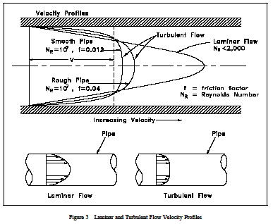
As you can see, for a given flow velocity, the sharper and pointer the profile, the more shearing, the more energy and pressure loss. The issue is compounded for a fixed flow rate as decreasing diameter requires increasing maximum velocity (a longer parabola).

Shear stress is what results in the pressure gradient along a pipe. I’ve added separate pump tube and pipeline diameters to the calculator, so you can see what a difference it makes.

Keep in mind it’s a general calculator. It uses the pump details to calculate a flow rate, but you could equally just type in any flow rate you want and it will tell you how much power you need. You can also use it to calculate sections of the pipeline and then add them up, and it will tell you the pressure drop (which is the pump outlet pressure) - and as long as there are no branches, in your pipeline the flow rate will be the same everywhere (conservation of mass, and assuming your fluid is incompressible, which is pretty true for most liquids).

The one important thing it doesn’t account for is bends in the pipeline, but as a very rough rule of thumb just add 15-20% for these. In a more thorough analysis where you know the actual pipeline layout you would include additional head loss factors for bends and joints. These have been determined empirically so you just have to look them up.

The other big problem with glycerin is it’s viscosity is very sensitive to temperature. I got the 300W with pure glycerine at a temp of 18°C - not unreasonable first thing in the morning.

Bumping the pipeline diameter up from 12mm to 50mm will land you a massive drop in flow resistance.

It’s important to keep in mind that ‘suction’ doesn’t exist - liquids and gases cannot pull, they can only push. There’s only high pressure and less high pressure ptessure down to 0 - which means you’re limited to a ‘suction’ of atmospheric pressure plus a bit more depending on how high your sump level is above your pump.

In order for any real world fluid to flow through a pipe, there must be a higher pressure at the inlet than the outlet. This means if you’ve got a pipe feeding your pump, the pressure at the pump inlet is lower than it is at the sump. The longer and narrower the feed pipe, the lower the pressure at the pump inlet.

Positive displacement pumps, like peristaltic pumps, add energy to the fluid primarily by increasing the pressure of the fluid. To help your pump out as much as possible you want to maximize the available pressure at the pump inlet - that means run the biggest fattest, and shortest pipe you can to the inlet, so that it loses the least amount of pressure flowing from the sump to your pump.

Ideally, from an energy efficiency point of view, have no pipe at all to your pump - instead, submerge it.

The take home message here is bigger is better. Get a much more powerful motor than you think you’ll need, and for a given volumetric flow rate bigger pipes are more energy efficient.

4 Likes

That’s pretty informative. We did a Prac at UniSA last year called “Losses in a Piping System”. Take aways from that are that fluids hate changes. Diameter, bends, valves and all the rest. Also, I suspect Ricky’s polymer tubing has a fairly rough surface if closely inspected (microscopically) and that would add to the issues. Mitigation here is the key to Ricky getting a good result.

5 Likes