Motorising and control of Dobsonian telescope

Hey @PETER298297,

I tested a unit here with varying loads and confirmed the supplies output 12V, despite being labeled 24V, definitely a fun discussion coming up with our supplier! Please reach out to us at support@coreelectronics.com.au, and we can assist with the damaged Arduino.

Hello Ryan, Good news at my end, I have the stepper motor rotating,and am able to edit motor speed and number of rotations.

I am not powering the Arduino controller from the plug pack, only from PC USB 5 V. But, using Plug pack 12 V to power the stepper motor via the TMC 2209 motor driver (5 V from the Arduino is providing 5 V logic input). All good, no overheating issues.

I am being held up at the moment with machining of the telescope drive components, so will spend time gaining experience with Arduino coding.

Strange with the plug pack label, not a good look ??

Leave the Arduino damaged board issue for the moment. the system is working, and I have more work to do before finalising the project.

One big issue will be obtaining a very slow motor speed, and whether the motor torque will be adequate, but I can keep going.

Cheers and Thanks

Peter

1 Like

Hey @PETER298297,

Thanks for the update on the Arduino board. Sounds like you’re making steady headway regardless, and it’s smart to focus on building experience with the code while waiting on the machining. If you run into any hurdles with the Arduino coding side of things, feel free to post your code here, happy to help troubleshoot or provide suggestions if needed.

Once you’re able to test low-speed operation under load, you’ll get a better sense of whether the stepper’s torque will meet your tracking needs.

Looking forward to seeing the next stage of the build come together!

Hi Ryan,

Telescope project is progressing, all mechanical components have been supplied. See image of belt drive system. The large sprocket is 3D printed, 240 mm diameter, the motor sprocket is 20 mm diameter, giving a reduction ratio of 12.

The lowest speed that I can run the stepper motor at so far is 0.3 rpm (with max microstepping of 1/64 and microSecondsDelay of 30000).

I am going to look at using higher microstepping (1/256), via UART.

The requirement is 0.01 rpm.

Can you pls clarify how I adjust current limit on the TMC2209 motor controller board.

I am using the formula Vref = I * (8 * Rsense)

I for supplied NEMA 17 step m = 350 mA (Adafruit XY42STH340354A, 12V 350 mA max)

Rsense = 0.05 ohms (label on Resistor adjacent to current limit potentiometer is “50” which is equivelant to 0.05 ohms.

Vref = .35 * (8 * 0.05) = 0.14 V

It is unclear where to measure Vref. from.

I have used the board ground and the rear solder connection on the trim pot (adjacent to the label “I limit 0 > 2A “ and the green terminal block. I have set the current limit Vref to 0.12 V.

Is this correct ? Some TMC2209 boards have a Vref pin for this purpose.

VRef on the chip is pin 17 - you can see the trace snaking under the three components immediately to the left of the potentiometer. According to the PCB diagram this trace goes to a large pad underneath the pot, so I assume the case of the pot is the measuring point. If you can adjust the value you read between 0V and 1.25V then you are looking at the correct point.

Is this a problem? If so, then what is the reason that you can’t set the delay to a figure higher than 30,000uS

2 Likes

Hi Geoff, I dont have a pin 17, the 3 components to left of the pot.. are the 3 leds, labelled F, B, and S. This board came in an Adafruit pack, part P6121, TMC2209 Stepper driver.

The case of the pot could be the point, I will give that a try, certainly not the pot adjustment screw, it is ceramic.

re delay figure. I have tried a higher value, ie 60K, and 35K uS, and found the speed increased significantly. The optimum was very close to 30K uS.

Will get back on pot case test.

1 Like

Pin 17 is on the chip, not the module. The trace might be buried in the layers of the board.

If using a value greater than ~30K increases the speed then you might be seeing the result of overflow from a signed int (15 bits). If you are checking the value of the processor ticks then check the size of the variable you are using to store the previous value - it should be a long. If you are using a delay function change the code to check the processor tick count (using a long).

2 Likes

@PETER298297
At a high level, I would think adding more gearing would be better then stepper pauses.
i.e. The objects in the sky dont stop moving so any non movement of the scope will have some level of streaking. While the human eye would tend to ignore it, the camera will tend to pick it up.
As such I suspect the least amount of pausing on the motion the better thus more gearing if possible

0.3/0.01 = 30:1
side benefit of going from fast to slow motion is higher toque at the scope mount from the motor.

2 Likes

Sure, pin 17 is shown on the TMC2209 schematic, but where does it go to ???

The pot metal case does not give a voltage signal at all.

I have checked the voltage range between gnd and the single rear solder connection on the pot base. (as previously mentioned). This solder point is almost certainly the centre tap of the pot.

There are 3 solder connect points on the pot base, 2 0n one edge, and one on the opposite edge.

The range is from 0 V to 1.2 V, so I reckon this is the Vref point.

1 Like

Telescope project has come to a major review stage, as typically protype developments do.

I am not able to see a way to reduce the stepper motor speed to an acceptable slow rate.

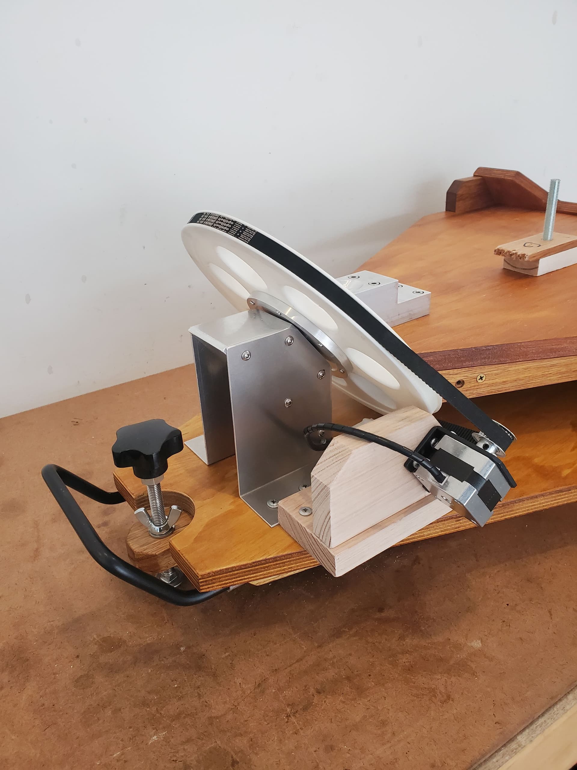
        The telescope must rotate at 15 deg / hr. The reduction ratio of the stepper motor sprocket / timing belt drive is 12:1 (20 dia, driving 240 dia.) This means that the stepper motor is required to rotate 180 deg per hour (1/2 revolution per hour, or 0.008 rpm).

I have calculated the stepper motor performance using the following settings - (200 full steps / revolution, 64 micro steps / full step = 12,800 steps / revolution). This results in ~ 1.8 steps /sec, and a step delay of ~ 560,000 micro seconds (~1/2 sec.).

Surely this will result in massive vibration….(not good for a telescope).

One option would be to replace current stepper motor with one with 400 steps / rev, and crank up the micro step rate to 256 (I am using aTCM2209 motor controller which can be configured via UART to give a maximum of 256 micro steps).

This will give ~14 step / sec, and a step delay of ~ 70,000 micro sec. However, I don’t believe this will result in the very slow speed that is required.

To date I cannot run the stepper motor slower than 0.17 rpm, at 30,000 micro sec delay. (Geoff did offer a potential explanation in an earlier post). If I reduce the step delay, the speed increases, as expected. When the delay is increased above 30,000 the speed increases, not as expected …?

Are there any guidelines as to what micro sec. delay should be aimed for (to give a very smooth motor rotation). Intuitively a high number of short delay’s should give the smoothest rotation.

The other option would be to add a reduction gear box to the stepper motor. A planetary low backlash reduction gear box (to suit NEMA17 stepper motor), with a reduction ratio of about 20:1 would bring the stepper motor speed from the current 0.17 rpm down to the required 0.008 rpm.

Any ideas, comments would be appreciated.

Hi Peter

I think that would be your next option. I have not had a lot to do with steppers but I think there is a limit to this micro stepping. You get to the point where the power, repeatability and holding position suffers beyond practical use.

Keep in mind also that if you are using the output pulses for telescope control there will be X pulses per revolution. That is the resolution you are stuck with and micro stepping will not alter that. Increasing the drive ratio will also improve your angular resolution per pulse.
Cheers Bob

1 Like

I’m not quite sure of the objective here. Your description implies that the movement needs to be as close to continuous as possible. But what usage of the scope requires that continuous motion? Why isn’t it possible to fit that usage (eg, a photograph) into the time between each incremental movement, after allowing for settling time? By syncing the observation to avoid the step you would obtain maximum stability. So the real criteria would be not how small each step should be, but how few steps you can get away with but still achieve sufficiently frequent observations with a stationary setup by allowing maximum settling time.

At very slow speeds microstepping is a big help with stability because it definitely reduces the vibration induced by the motor itself. Presumably it also reduces vibration induced by the inertia of the telescope and mount because the movement is smaller.

Re current limit: Pin 17 of the chip runs across to a large pad under the trimpot. I assumed this pad would be the case, but it could just as easily be one of the tabs. If you can get a reading of 0 to 1.2V to the tab then you are measuring the correct thing.

1 Like

While it is correct that using microstepping does not always increase accuracy, it is not correct to say that microstepping does not alter the number of pulses per revolution. When the controller is in microstepping mode the pulses per revolution changes by the microstep factor. You may be referring to the fact that the torque available per step also reduces, and may become insufficient for proper positioning. This will be corrected when the microstepping next catches up with a full step, or at least a step that has sufficient torque. But the microstepping definitely adjusts the steps per revolution - when the microstep value is changed the steps per revolution has to be recalculated accordingly.

1 Like

Hi Peter
Add on to Jeff’s comments above
If you need continuous rotation an alternative would be a brushed DC motor under PWM control. This would require a very great gear ratio, possibly 2 or more gear boxes in series.
The advantage here is that you can run a motor very slowly and still have reasonable torque. The speed would also be adjustable.

The possible down side here is that if you want to run the motor VERY slowly I don’t think you will be able to use most of the driver boards on offer that use a H bridge for direction control. There is a reason for this which I have gone into previously but nobody seemed to want to know so I will not elaborate unless someone is seriously is interested. Just believe me when I say that for very slow operation a simple Mosfet, Flywheel diode (fast one ) and a DPDT relay for direction control will yield best results.
Cheers Bob

1 Like

@Jeff105671 for all practical purposes, when on earth all the stars move at a rate of 15 deg per hour (or close enough). When taking a photo, to collect as much light from the star(s) you want a wide aperture AND a long exposure.
By having the telescope rotate at the same rate as the earth, to the view finder in the telescope/camera feed, all things should appear still i.e. the mount rotation cancels that of the star locations.
Any pause in that rotation will result in the stars appearing to move in the view of the scope/camera thus result in a streak on the “film”. So the least amount of movement the better results they will get for the astro-photography.

So I see the key objective to have as constant movement as possible to match the 15 Deg/hour (and less move, stop, move, stop as can happen).

1 Like

Hello Jeff, Michael, Robert,

Thank you all for comments and advice.

Firstly apologies Jeff for mis spelling your name.

Michael is correct about the key objective of constant movement.

There is an astrophotography “stacking” technique now in use that takes a number of very short exposure images and stacks them one on top of the other to get adequate light intensity. Possibly, image shoot could be synced to the micro step pulse.??

Without motor control of telescope movement, even with relatively low magnification, the sky image (via eyepiece or camera) disappears within 30 seconds from the field of view and you have to manually push and pull the telescope to get the image back into view, very frustrating at times.

There are a number of commercially available motorised telescopes available that are not expensive, so would need to be of a simple design.
As well, there have been a number of Astronomy groups that have converted basic telescopes to motorised drives. I know that stepper motor together with gear boxes have been used in these cases (especially the more recent ones).

re pin17 Vref on the TMC2209 board. I have the V1 board, which has a slightly different layout to the V2 and V3 boards. These later boards have 3 metal eyelets on the board, one of which seems to be the touch point for Vref.
Cheers Peter

1 Like

Hi Jeff
Sorry I should have been a bit more explicit.
I think we got a bit mixed up here. I was referring to any output pulses from an encoder or pulse generator fitted to the stepper shaft which will have a number of pulses per stepper revolution which I don’t think will change . Of course the number of input pulses required to get 1 revolution will change with the micro stepping value.

I should have made this a bit clearer. Getting slow.
Cheers Bob

1 Like

I was aware that continuous smooth motion was the gold standard, but I assumed that was not going to be achievable within the budget and engineering capability that was available. Smooth continuous controlled motion can be achieved with a high speed motor and driver, such as BLDC, but the engineering required in the gearing to achieve that becomes very expensive. For instance it would probably involve large ball screws in order to deal with the backlash that is otherwise very difficult to remove from highly geared systems.

So the other option is to use a stepper or servo, run it at a slower speed with lower gearing and try to account for the stepping. The choice is between precision mechanical engineering and tricky electrical control - not an uncommon choice in industrial engineering.

An intermediate compromise is a slower motor which necessarily means a certain level of jerkiness, a level of gearing that is feasible in a small system, and image adjustment and processing to negate the shake. This includes allowing settling time, syncing the shot to the movement, image stacking, higher sensitivity sensors, and image stabilization (either in hardware or in post-processing). So my comment that the starting point might be to determine how few steps you can get away with still stands. That will determine what gearing you need with a stepper or servo with a particular resolution, and whether that gearing is feasible. If it’s not then you may need to look at different engineering. If it looks feasible to achieve the required result with a manageable step rate then you can go ahead with that and move on to looking at the options available for ameliorating the intermittent movement. Of course there are still plenty of unknowns in that sort of assessment, and re-evaluation might be required at any point, but plotting a path forward is the important bit.

1 Like