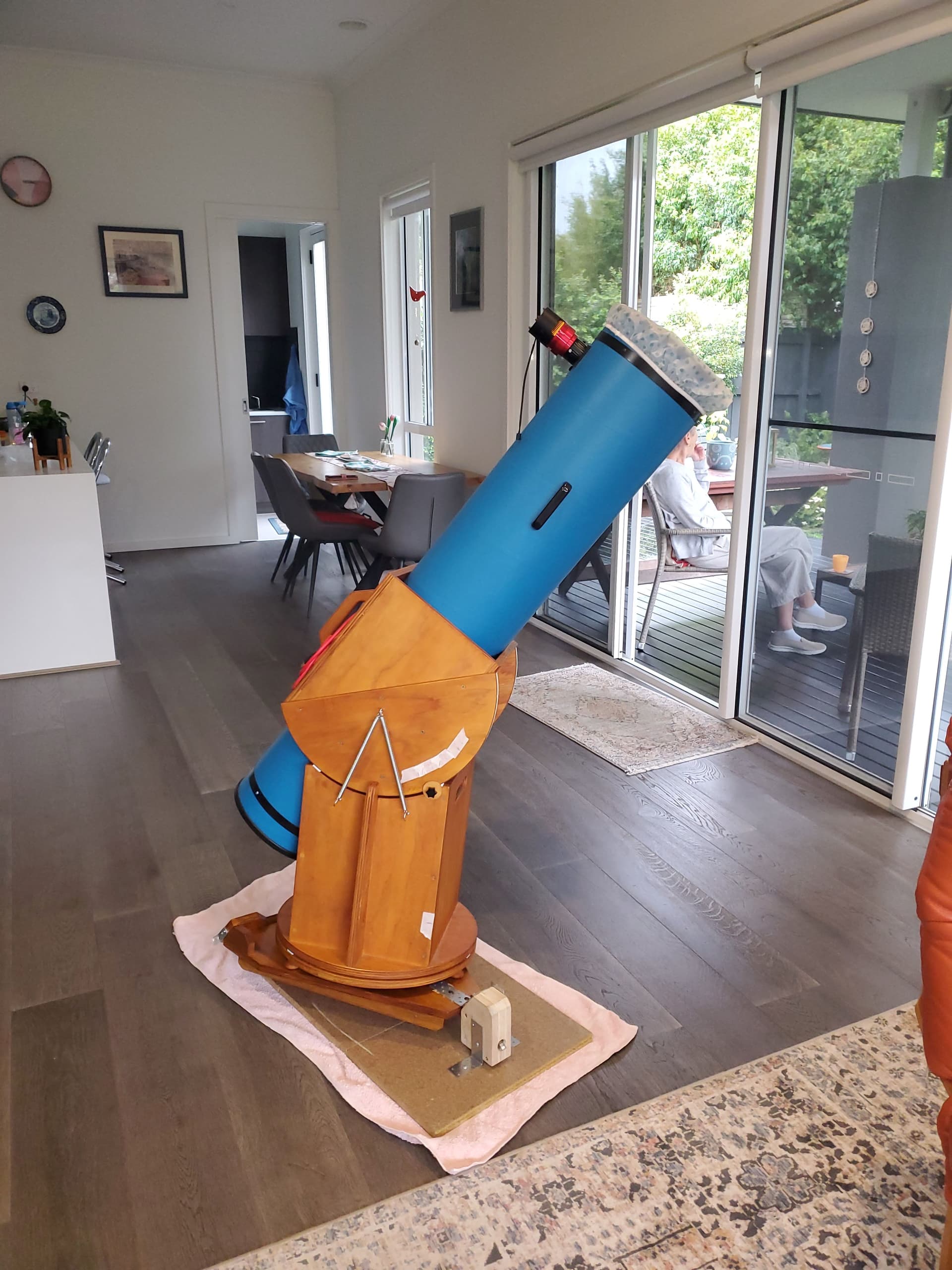
I am in the process of adding a motor drive and control system to my 200 mm Dobsonian telescope.
The mechanical aspects of the new platform have been completed, and will give improved precision and rigidity to the assembly.
I am now ready to add the motor and control components, however my knowledge of this topic is limited.
I would appreciate help and advice from those who have experience of this stage.
I do know that a motor (stepper?), reduction gearbox unit, a micro controller, a motor driver is required
A 12V supply is preferred, but could go to 24V if required.
The telescope axis can be driven from either 1. North end via a 200 mm dia wheel (via a toothed timing belt, and small dia sprocket), or 2. South end via an 880 mm dia circle segment (via open timing belt and sprocket).
Images of telescope can be supplied.
Thanks in anticipation.
Peter
Hi @PETER298297
Welcome to the forum, great to see your project coming together! You’re definitely on the right track so far.
For precise tracking, a NEMA 17 stepper motor is a great choice. They’re accurate, reliable, and well-sized for telescope drive systems.
To control the motor, you’ll need a stepper driver. Here are two solid options:
- TMC2209 – ultra-quiet and supports microstepping up to 1/256
- DRV8825 – higher torque support, simpler to set up
A standard Arduino Uno is a great beginner-friendly controller and has lots of support in the DIY astronomy community.
For power, a 12V plugpack is ideal, it’s enough for the Uno and one NEMA 17 motor via the driver. You can power the Arduino via the barrel jack or the Vin pin.
If you’re planning to use timing belts for drive reduction (e.g. GT2 or HTD pulleys), you likely won’t need a gearbox, I think the mechanical advantage from large discs (like your 200 mm or 880 mm ones) plus microstepping gives you all the resolution you need.
Lastly, feel free to upload some photos of your setup, it’ll help the community give more specific guidance on mounting, layout, and belt routing!
Hi Ryan, thank you for quick reply. I have attached some photos. I did forget to mention that this is an equatorial platform, but I am sure it is obvious.
The virtual platform axis is tilted at 38 degrees (Melbourne latitude).
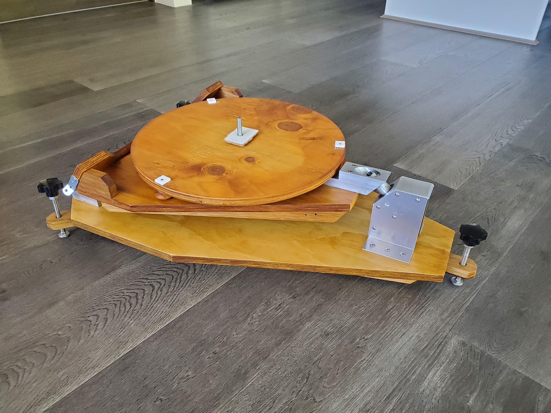
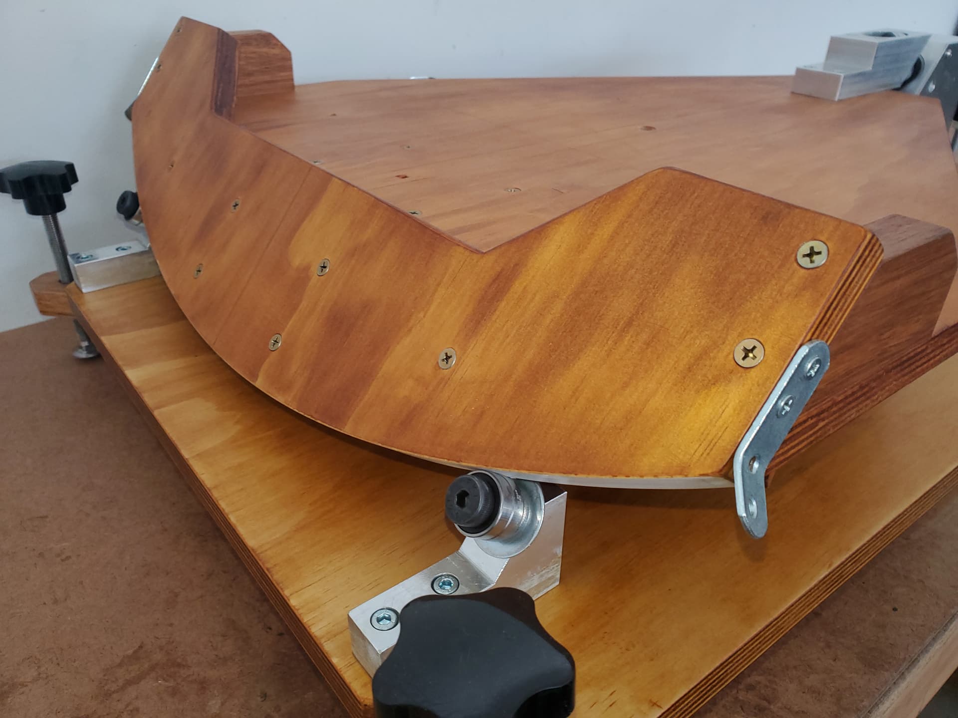
the telescope image is showing an earlier prototype platform, which has now been replaced (see images platform 1, 2).
re drive options - platform 1 image shows a 20 mm wide spacer between the platform support and the base plate bearing support. This can be removed and a 200 mm diameter toothed drive sprocket fitted.
The motor could be mounted to the side of the base bearing support housing.
Alternatively, the motor could directly drive via a toothed sprocket to an open timing belt fixed to the underside of the circle segment (880 mm dia).
I am not so sure of using a friction drive, but happy to consider other options.
Cheers
Peter
Hi @PETER298297,
Thanks for sharing the extra info and photos, that clears things up a lot. The equatorial tilt and those large arc segments definitely open up some good options for precise tracking!
Between the two drive options you mentioned, the 880 mm arc with the open timing belt is likely the better choice for smooth, consistent motion:
- The large radius gives you a natural mechanical advantage, meaning the motor turns more slowly and smoothly to track the sky, ideal when paired with microstepping.
- Open belts fixed to the arc segment (with adhesive or low-profile fasteners) can work really well, especially if you get the tensioning right.
I believe that the 200 mm sprocket option would still work fine if you want a more compact layout, but the smaller radius means you’ll need finer control from the motor to achieve the same tracking accuracy, something the TMC2209 can handle, but it may be a little less forgiving mechanically.
And yes, I’d generally avoid a friction drive in this case, even small slips can cause noticeable tracking errors over time.
Looking forward to seeing how it progresses, feel free to keep us updated with your build!
Hi Ryan, I have a few comments and a few more questions, hope you don’t mind.
I agree the 880 mm arc is probably the better set up re precision tracking. If a 2mm pitch, pulley and belt is used, (13 mm dia pulley will give 20 teeth), that will give a gear reduction of about 68:1 (880/13). There is a 12 tooth sprocket available (about 8 mm dia, probably too small).
Eliminating a gearbox from the stepper motor would be a real benefit as well (backlash).
How can I calculate the stepper motor output speed (in combination with micro stepping and the 68:1 gear reduction) ?
Is there an optimum balance of mechanical gear reduction and micro stepping to achieve the very low speed telescope platform rotation ?
The actual platform rotation speed requirement is 15 degrees per hour (1 hour viewing in a 24 hour day).
My calculations give 3 revolutions per hour for the stepper motor, that is 0.05 rpm ???
Is that possible ?
re NEMA 17 stepper motor.
There are a lot of stepper motors listed .ie. with a torque output upto 80 Ncm, 0.9 deg and 1.8 deg step angle, what specs do I require ?.
re Power supply.
Could a 12V battery pack (from a cordless power tool) be used instead of the plug pack, so as to give portability ?
Hope I am not too demanding, I am finding this project very interesting and challenging.
Cheers
Peter
Hi @PETER298297
So with a microcontroller it would be possible to define your target rotation and the time that it would take to move between its starting and finishing points. Something like the below would work for an Arduino Nano to use a TMC2209 Stepper Motor Driver. It will do the heavy lifting in terms of calculating the output speed.
const int stepPin = 2;
const int dirPin = 3;

// Stepper config
const int stepsPerRev = 200;
const int microstepping = 16;
const float gearRatio = 68.0;

void setup() {
  pinMode(stepPin, OUTPUT);
  pinMode(dirPin, OUTPUT);
  digitalWrite(dirPin, HIGH);  // Set fixed direction
}

// Calculate time between steps for ~2.83 RPM
void loop() {
  float rpm = (1.0 / 24.0) * gearRatio;  // ~2.83 RPM
  float stepsPerMin = rpm * stepsPerRev * microstepping;
  float delayMillis = 60000.0 / stepsPerMin;  // Delay between steps in ms

  digitalWrite(stepPin, HIGH);
  delayMicroseconds(200); // STEP pulse
  digitalWrite(stepPin, LOW);

  delay(delayMillis); // Wait before next step
}
In terms of what you need for torque, it will depend on the force required to move the telescope, generally speaking though having more torque than required is always going to be better, for step angle 0.9° motors will be more expensive but will have a higher resolution and less vibrations.
You could definitely use a drill battery for this, you would likely need a DC-DC Adjustable Step-down Module 5A 75W | Buy in Australia | CE07271 | Core Electronics or two (power tool batteries are usually 18V+) to drop down to 12V for the motor and also 5V for the microcontroller.
Hi Dan,
Components have arrived, and I have made a start.
I have decided to start off with the original recommended plug pack, it is a lot more convenient at this prototype stage.
I have assumed that I will need a barrel jack splitter so that I can take 12V from the plug pack to the Arduino board power input AND also to the +/- terminals on the terminal block of the TCM2209 board.
Is this correct ?
I have decided to connect the stepper motor (via a timing belt and two pulleys) to the 200 mm dia wheel at the rear of the telescope. Again this a simpler method at this stage.
If I can’t get a slow enough rotation speed, I can drive off the front large wheel at the front of the platform.
Thank you, cheers
Peter Hill
Hey @PETER298297,
Great to hear the components have arrived and you’re moving ahead with the build!
Yes, your assumption is correct, a barrel jack splitter is a simple way to power both the Arduino and the TMC2209 driver from the same 12V plug pack. Just make sure the splitter is rated to handle the current draw of your motor under load.
Starting with the 200 mm wheel at the rear sounds like a good move, it’ll be simpler to test and debug your system that way. If needed, moving to the larger arc at the front later will give you even finer control (at the cost of a slightly trickier setup).
A stepper will go as slow as you want. At 200 steps per revolution (ie, even without microstepping) to get 0.05 rpm you would do 10 steps per minute or one step every 6S. That gives ample scope for calibrating: the Arduino clock will not be accurate, although it will be quite consistent. You can increase the step rate using microstepping, and that may help improve the smoothness, but if you are doing photography you can time the photos so they do not occur during stepping, so smooth motion might not matter.
Hi Ryan, I have the barrel jack splitter in place and noticed something that I don’t understand.
With the 12V plug pack supplying the Arduino uno board (via barrel jack IN), the 5V power pin is indicating 8V, and the 3.3V power pin is indicating 3.3 V, as it should. USB is not connected.
If I remove the barrel jack input, and connect the USB cable from PC, the Power voltages are 5V, and 3.3V. This is as expected.
If I connect both barrel jack from plug pack, and also USB from PC, then power voltages are 8V and 3.3V, as when barrel jack was connected on its own.
Do you have any thoughts on the 8V ?
I am intending powering the TCM 2209 motor driver from the Arduino 5V power pin.
Cheers
Peter
Hi Peter
I believe the UNO has a 5V linear regulator on board to reduce the 12V to the required 5V. I would suggest this regulator could be suspect.
I am pretty sure that 12V is the absolute upper limit for the barrel jack input.
The 5V when USB connected is normal as this becomes the power source and the regulator is not used.
Cheers Bob
Just spotted this
I don’t think you should use this 5V for motor power. Use it to power the electronics OK but I think Motor power should be separate.
The 5V regulator on a UNO is a LM1117 or equivalent. It is designed for an input of up to 15V so your 12V supply is fine. But if it is outputting 8V or thereabouts then it has failed, and it likely has taken the MCU with it, as the ATMega328P has a maximum voltage rating of 5.5V. Are you sure you are measuring the voltage correctly, and in particular that you are measuring to the correct earth?
The USB supply does not go through the regulator, so the 5V you are seeing when that is connected is the 5V direct from the USB. When both are connected (which is not recommended) you will read the voltage as the higher of the two supplies.
The 3.3V is supplied by a second regulator that is powered from the 5V supply. If the 5V supply really is running at ~8V then the 3.3V regulator will continue to run as normal.
Note that there are some clones of the genuine UNO that may have a slightly different arrangement.
Hey @PETER298297,
As Jeff and Bob have pointed out, 8V on the 5V line is not normal and indicates a fault. An easy way to check if damage has occurred is to Power the Arduino via USB only (disconnect the 12V supply and barrel jack splitter).
- Connect the Arduino to your PC via USB.
- Try uploading a simple sketch (e.g., Blink) to confirm the microcontroller is still working.
If that works, disconnect USB power and power the Arduino with just the 12V barrel jack (no splitter).
- Then measure the voltage between the 5V pin and GND pin as shown below.

Let us know how you go with those measurements, and feel free to provide any images of your setup as that will assist in determining whats going on.
Hi Ryan, Jeff, Robert
Firstly, thanks for your interest and support.
Something is certainly not right.
Test 1 with USB connected only. 5V on Arduino power pin, Blink sketch working correctly.
Test 2 with 12 V plug pack connected to barrel jack and splitter removed, USB disconnected. 8.7 V on power pin, Blink sketch working correctly.
Test 3 as for 2, but with splitter in circuit but leg 2 not connected (splitter leg 2 is the 12V supply for the TCM 2209 motor driver), 8V on power pin, Blink sketch correct.
Test 4 as for 3, but with splitter leg 2 connected to TCM 2209 + / - pins on terminal block. 8 V on Arduino power pin, Blink sketch OK.
The Measured 8 V varied slightly, 7.7 - 8.7 V.
Plug pack output measured at 12 V
Cheers
Peter

Your first reference indicated the 5V pin, while above you have mentioned ‘power pin’. I assume you are measuring the voltage on the Arduino at the pin marked ‘5V’ and not the pin marked ‘VIN’. You have the red wire on the 5V pin, so I think that’s a pretty good assumption.
In that case I would guess that the power regulator on the UNO is faulty, but the UNO is still managing to function despite the voltage being well out of the range of maximum allowable voltage. It is quite possible (but unusual) for a device to operate well beyond its specs, but that won’t last for long. I would recommend not powering it from the 12V supply and use it only from the USB supply until you can get a replacement. Or, if it suits the project, commit to only using the USB supply for the UNO. Or, get a 12v-to-5V adapter, power it from the 12V supply and connect that to either the USB input or the 5V pin.
If you continue to test it, don’t connect anything to the IO pins, as it is likely that they are being driven outside the device specs, and anything you connect could be damaged.
/Edit
If I look closely at your image, I believe I can see the mark on the regulator indicating the point where the magic smoke escaped. I think the death of the regulator can be confimed.
Edit/
Hey @PETER298297,
Confirming what Jeff has said above, this mark on your regulator generally indicates that it’s died and released smoke at some point:
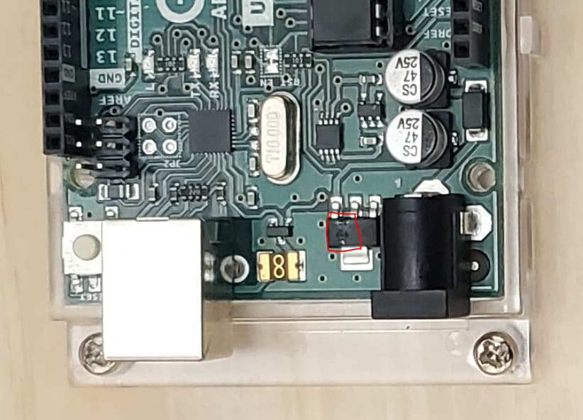
It’s impressive that the board is still running with 8V on the 5V rail, but that definitely won’t last if you continue powering it via the barrel jack.
Arduino regulators are usually quite robust, so it’s possible something in the setup triggered the failure. Are you using this 12V plug pack?
Also, do you have a part number or any details on the splitter? If the polarity is reversed (e.g., center-negative instead of center-positive), that could easily explain the regulator damage.
Hi Ryan,
I have attached some images.
-
Regulator - YES there is a strange mark on the top ??
-
Box - the plug pack box lists as 12 V 2 A, but it has a different part no. M8936D
-
Label on PP - has part no. 8968C, BUT, it indicates Output as 24 V 1000 mA ??? I checked the plug pack before power up, it definitely measured 12 V. I have just checked again, and it is 12 V output.
I am absolutely certain that the PP is 12 V output, irrespective of the label.
I am not using the plug pack to power the Arduino via barrel jack. I am only using USB input from PC.(5 V). However I suspect it will be OK to only use the PP to power the TCM2209 motor driver.
I have checked the splitter for polarity reversal, all good, it is centr - positive.
For Jeff, - have not used Vin pin at all.
My next step is to get the stepper motor rotating etc … I intend using USB 5 V to power the Arduino, and the PP 12 V to power the motor via the TCM2209 motor driver. Is this a good idea ?
Cheers
Peter


Yes - that is the best arrangement. Be sure that the ground from the 12V supply is connected direct to the Arduino ground.
I would not trust that power pack. It isn’t unknown for an item to get repacked into the wrong box at some stage of its handling. To be absolutely sure of the voltage it should be tested under a decent load - say 200-500mA. Without the sort of load it is designed for it is possible to get a spurious reading.
The Arduino regulator has good protection against both input overvoltage and output short-circuit. The most likely form of failure is overvoltage input combined with a load that puts the whole device over its power dissipation maximum, where neither overvoltage nor short-circuit protection cuts in, but it still overheats.
Hey @PETER298297,
I’ll test these power supplies here to confirm if it’s an error on the label or something else and get back to this post tomorrow ![]()
In the meantime, as you continue testing your set-up, this is a good power arrangement.