Hi!
Just after some reccomendations on which items would work best for this motorised lifting platform we’re trying to mock up (to dispense small products). Similar to the image below- except with a stepper motor:
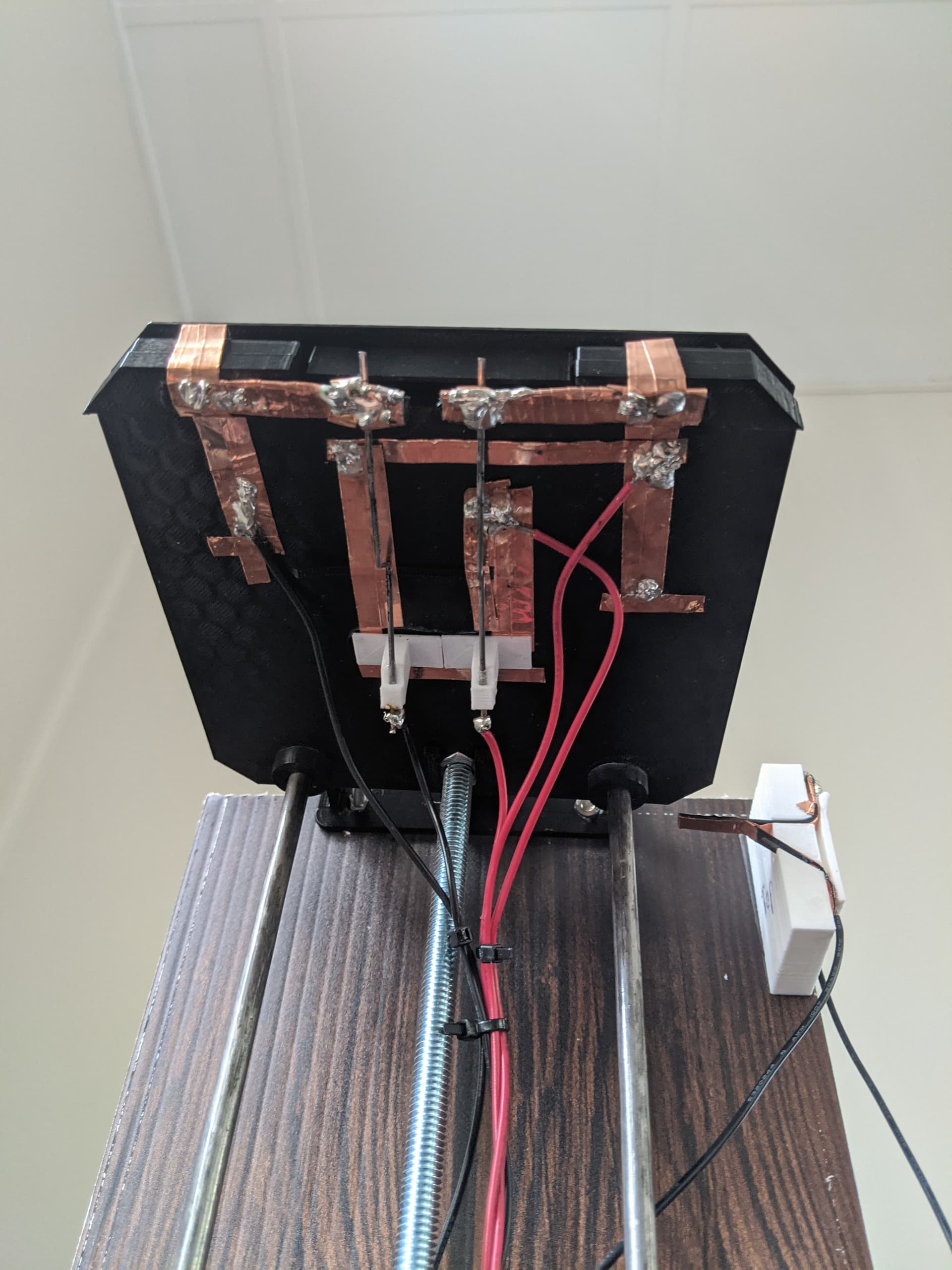
I’ve tested this with a single motor, single battery and two switches- along with an alternating switch on the platform, and its just too finnicky to get right. See pics below:
It’s all pretty rough at the moment.
So we were thinking to use a stepper motor, we just dont know what to get to program it. And which switches would work best in this case.
Then all we want to do is program it to recognise when a product is on the platform and lift up to a certain point and stop. Then go back down to a certain point when the product is lifted.
Hope that makes sense,
any questions- just let me know
Usually with stepper-driven small machines like 3D printers, microswitches are sufficient, something like this should do the trick:
Our Makerverse motor driver should be all good to plug into something like a Pico, only catch being that it may be a little noisy, so going to a driver that can microstep with sine waves like the TMC series may be a next step after proving it works with the simple motor driver.
If you have any other questions that come to mind, let us know!
-James
Hi Robert,
Main reason is to slow down the motor and be able to control it (eliminate the need for any switches to turn it off at the top and bottom- and only have the one switch on the platform to make it go up to a certain point and stop, and then go back down to a certain point when its untriggered)
Would also be awesome if it were quieter than a normal motor.
Thanks- so the Microswitch would be what goes in the platform? Would be great if the whole thing only needed the one switch (like my reply below).
Ahh yeh trying to bring down the noise with the switch to a stepper motor too.
What would you reccomend to use to program the switch with the stepper?
(p.s sorry my tech knowledge is pretty basic- in fact I’ll have to search up how to program the stepper haha)
Hi Anneke
A geared brushed motor with a screw feed to drive the platform would be pretty slow.
Could be done with 3 microswitches, 4 Diodes, 1 DPDT relay and a master switch to remove power from the whole thing. And a bit of wiring.
No Raspberry Pi, No Arduino, No stepper controllers or motor drivers. Simple wiring.
But basically I am a pretty simple person and hate complications when not needed.
Cheers Bob
Ah ok cool, so this would still allow for an automated system like the video link I shared before?
I’ll have to check with someone techy i know to explain how the microswitches, diodes, DPDT and master switch will be set up with the pressure activated platform.
Thanks for the tip- also not sure how this can be powerless (do you mean no battery at all?)
Hi Bob,
Oh sorry I just got confused when you said ‘to remove power from the whole thing’ hahaha you must have meant strength type of power. Of course it would need a battery haha
Thanks that would be great- only if you have the time, otherwise I should hopefully find someone to help me
S1 and S2 should be mounted so your platform stops where you want it to. There is no need to allow for overrun of the motor as D2 or D4 will stop the motor dead as soon as S1 or S2 open. D1 and D3 allow current in the reverse direction so the platform can be reversed and allow the switch to close again.
I have arranged the relay to default (not activated) to the down position.
S3 is to detect an object or load on the platform and has to be mounted on the platform. It is up to you how you do this. Have a plate on the platform hinged with a light spring so S3 is open with no load and closes with a load. The method I would prefer is to mount S3 under the platform and drill a small hole in the centre and arrange everything so when a load or object is placed on the platform the switch closes. Possibly operated with a small rod through the hole.
Operation should be as follows. With power applied, S4 closed.
With no object the platform is at the bottom. When an object is placed S3 closes, Relay operates reversing the motor volts. Circuit is made to the motor via D1 and NC contact of S2. Platform rises.
Platform reaches top and S2 opens stopping the motor. The platform will stay there until object is removed.
Object is removed, S3 opens releasing relay. Voltage is reversed and now applied to motor via D3 and NC contact of S1. Platform at bottom, S1 opens so stopping motor and will stay until next cycle.
D2 and D4 are motor braking diodes and are connected in the appropriate polarity via NO contacts of S1 and S2
Notes.
Diodes need to be capable of the stall current of the motor. If this info is unavailable measure the resistance of the windings and calculate it. Take a few measurements when the rotor is moved to get the best commutator position and use the lowest reading. If you leave the meter connected turn the motor VERY VERY slowly as it will be a generator and could damage the meter.
Battery or supply voltage will depend on the motor used.
Relay voltage will depend on supply voltage. Needs to be DPDT relay. OMRON LY series are good. Be a bit careful whichever one you use. Some have a flywheel diode fitted internally and thus are polarity conscious.
Initial set up.
Check and double check wiring. Although not shown it may be a good idea to have a fuse in the supply line. Directly either side of S4. Just in case of unseen mistakes.
Start with the platform half way up.
Apply power (close S4), With no object on the platform it should start DOWN.
If not REVERSE THE MOTOR CONNECTIONS ONLY. DO NOT REVERSE ANYTHING ELSE or the diodes may well be the incorrect polarity with disastrous results.
The set up should work as expected.
The circuit is really an adaption of a pretty standard limit switch arrangement I have used many times in the past. As a limit switch set up it works very well so I am confident this will be OK. All done with no fancy electronics. Keep it simple is the motto.
Cheers Bob
Thanks for sharing your insight and experience, I’ll be bookmarking your post as a top resource to refer people to when we have questions RE limit switches in the future (and I’m sure we will).
I’ve attached a rotated version on your diagram below for easier readability.
Hi Bob,
This is incredible!! Thank you so much for taking the time to explain everything- this is perfect to get me started, I just have to order the right parts now.
Love how simple you keep it, even I understand it.
Will let you know if I have any questions when I get around to testing it all out
Hi Anneka,
Just a reminder all this suits a brushed motor. NOT a stepper. A geared brushed motor can be pretty slow, they vary quite a bit. Decide on your lifting system first then work out how fast the motor needs to spin.
Cheers Bob
Currently trying to find all the specific parts to order,
I’ve found some Microswitches and a rocker switch for the master one.
Along with a motor (99:1 Metal Gearmotor 25Dx54L Mm LP 12V) (please advise if you had a different type in mind).
And for the DPDT, I found this:
The battery I have currently is just a milwaukee rechargable 12V, 2.0Ah / 24Wh battery. Though might try and find something with lower voltage if needed.
The only thing I want to check is which particular Diodes I need for the relay. Happy to order multiple types to try out (theres just quite a few to choose from).
Hi Anneke
Relay. Yes this or similar is what I had in mind. I only suggested Omron Ly series as historically I have found them very reliable. The bases and retaining clip are available if you want screw terminations.
Motor, This is entirely up to you. Depends what speed you want out of the motor at the user end (shaft) which will be influenced by your lifting mechanism (screw feed etc). As long as your voltages are all the same. Mixing can be messy.
Diodes. As long as they are rated at reverse 100V or more and must be able to stand the stall current of your motor. Power diodes are OK for this application. Last time I did this the diodes were large power rectifier bridges as the motor was quite large, several amps.
Up to about 800mA or so (0.8A) the 1N400X series are OK. Anything above this and you have to look larger.
In deciding what you need you need to start at one end and progress in a logical manner. I get the impression you are starting and trying to make or get other people to make decisions from the middle. This will finish up a dogs breakfast.
I would start at the platform, how fast do you want it to travel.
Lifting mechanism, screw type linear actuator, toothed belt or other.
How are you going to drive it, Directly, gears, belt etc and what reduction ratio if any happens here.
This will pretty much determine the shaft speed required from the motor and enable this selection to be made.
Once a motor / gearbox combo is selected you should now have an operating voltage. If you intend to use a 12V battery this will have an influence on motor selection. These two factors, motor and power supply should be considered together.
This will determine the relay operating voltage.
The diodes will mainly be influenced by the stall current of the motor so unless you go for big ones will have to wait until the motor is selected.
Cheers Bob
PS Re motor. Just looked up the one you quoted. That is the type of thing I meant. Exactly which model will depend on your required platform speed and screw thread pitch (in the case of screw feed selection).
Be a little bit careful however as this motor has a 4mm shaft diameter and this has to couple to your lifting mechanism. A lot of these things accommodate 6mm or 1/4 inch diameters.