POLOLU-2808 Mini Pushbutton Power Switch as Momentary to Latching Convertor

Hi,

Chasing some help with the POLOLU-2808. Recently purchased with the intent to have a momentary switch toggle a circuit normally activated by a latching switch. There are case packaging restrictions that make simply swapping to a latching type switch not ideal, hence the preference to maintain the currently used momentary switch.

Gained the idea from this youtube video: Momentary to latching converter - YouTube

Attached is an image of my install and the current wiring, but the circuit currently still operates as a momentary switch (ie: power to device is only on while the switch is pressed) there is no toggle or latching operation beyond staying in the off state. The LEDs floating to the top left normally will flash continually when power is on, and the top right two brown wires are where the latching switch would normally be installed. The third single LED off the POLOLU-2808 is not ‘needed’ for the normal operation, but was installed to more visibly show the state of the POLOLU-2808.

I’m new to these types of components, so any guidance to get this to operate as a simple on/off switch is appreciated!

4 Likes

Hi Matt.
According to the text on the product description page that should work. UNLESS as the text says the switch in use has excessive “bounce”. That is when the switch makes and breaks several times over a period. Most switches exhibit this problem but some more than others. The same thing occurs when the switch is released. Use of a really good quality switch will minimise this problem but you might help things if you fit about 0.1”F capacitor across the switch. Might work, might not. Depends on what the switch is actually doing. The latching system seems to be a proprietary circuit used in other applications and not for general publication. I can understand that.
Cheers Bob

5 Likes

Hey Matt,

Debouncing with an appropriately rated cap as Bob has suggested will likely help with the setup that you’ve got there. If you’re looking for a pre-build solution for your project, we carry an Adafruit breakout that should be easier to use/adapt to your current rig (rated for 14VDC up to 3A, but will get hot quickly if you run power that high constantly):

4 Likes

Hi Bob, Bryce

Thanks for the info!

The specific switch I’m using currently is significant to the setup, and is why I’ve ended up on this path to try and convert it to a latching setup. Space is quite tight, but I am also open to other ways that may not use the Pololu-2808 to convert this signal to a latching type switch.

I’ve just tried the 0.1”F capacitor advice across the positive and negative terminals of the switch, but did not get the desired result yet. The circuit does switch on, but does not stay on and the switch itself did seem less responsive when connected. Is this the correct way to connect this? The capacitor I tested is a (old?) ceramic non-directional type rated as 0.1”F, can this affect the result? Is there a better option to try with this?

I’m reading 13.00V across the original switch terminals (brown wires)

Thanks for your guidance!

5 Likes

Hi Matt
Without having this in front of me it is a bit difficult to ascertain exactly what is happening.
What is that board the switch and connector are on. Is there any circuitry or components between the switch and connector. It is covered with yellow tape.

Should be OK as long as it is still 0.1”F.

Latching relay, pulse on/pulse off. which is an electro mechanical version of what you have got. The relay will take several milliseconds to operate so I don’t think switch bounce is a problem.

Can you check the switch in isolation with an oscilloscope. I realise that not every hobbyist has one of these on hand (but it would be useful if they did) but you may have access to one. This will show how bad or good the actual switch is.
Cheers Bob

5 Likes

Hi Matt
I have the feeling there is something not quite right here with connections.
You have 4 wires disappearing off the top of the pic. Where do these go. Could you put up a complete diagram or better pic.
Your current pic shows 2 brown wires going to “Vin” and ground. A red and black wire going to “Vout” and ground. Now when the switch operates “Vin” will connect to “Vout” so the question is where do the brown wires and the red and green wires from the other LEDs go. It looks a bit strange. How do you know which is positive and which is negative between the brown wires. This Pololu device is polarity sensitive.

As requested a better diagram please.
Cheers Bob

4 Likes

Hi Bob,

Here is a wider shot of the original image, note the brown wires ‘twist’ and swap sides before they end up in the connector:

This is the latching switch that normally plugs into the 5 pin connector, basicaly the component I am trying to replace with this setup:

The switch board covered with tape normally looks like this:


Though my understanding from the latch switch is that the two colour LED function is not usable through the signal normally sent to the LED on the latching switch, but isnt important to me as it only needs to indicate the switch is on for my function. The yellow tape is mainly a visual blockout so its not taken into this circuit. The board and testing seems to demonstrate the two pins i’m using on the board are for the switch alone and do not directly affect the LEDs already there. Hopefully this is confirmed in the pictures?

The current orientation for the brown wires was determined by only getting any reaction from the switch in this layout. Though I tested the outermost brown wire (connected to VIN) is the positive, and the second from the outside is the negative (connected to GND).

Unfortunately I dont have access to an oscilloscope, but the latching relay option could definitely be a possibility if this Pololu board doesnt work out!

Thanks so much for the help so far

1 Like

Hi Matt

That is a bit of a silly way to do that. You could easily do some permanent damage that way. Do you have a multimeter.
Those pics don’t tell much either. Are the brown wires the supply. When you said one is pos and the other neg I assume so. That being the case the only thing that would come on would be the single LED hanging off the Pololu board. Maybe you could have done some damage with your method of determining the brown wire polarity I don’t know.
Here is a sketch showing how this switch should be wired.


Exactly what you are trying to do here I still don’t understand fully so wire it up like this by just putting 12V (??) on Vin and some sort of load (LEDs etc) on Vout and see if the switch is still working.
There seems to be a push button on the device, does that work. That is what I would do first, see if the Pololu board has been damaged or still works.
Cheers Bob

2 Likes

Hi Bob,

Apologies, I should have clarified. I do have a multimeter and I did workout the postive/negative out before just connecting - I was guided by the youtube vid in my first post. When I have since tried to diagnose this non-function, I had attempted swapping these wires to see if I had done this backwards, but got no result at all having these reversed (confirming the polarity sensitivity of the device). Everything still works and I can repeat the momentary functioning of the switch when connected as shown in previous photos.

Short MOV file demonstrating current function: Dropbox - 20220129_060747000.MOV - Simplify your life

Hopefully the following makes sense: In normal function, latching the two brown wires will turn my device on. I am trying to create this ‘latch’ via the Pololu board activated by the momentary switch, to toggle an ON state, and then an OFF state alternately. Basically, mimicing the function of a latching switch, but restricted to using the push button switch visible in the photos. These two brown wires have a constant 13V through them.

Let me know what else will assist to clarify further - attached is a diagram of the way I currently have this connected, hopefully legible:

2 Likes

Hi Matt
You still don’t quite get it. Please refer to my sketch. If latching the 2 brown wires turns you device ON there one should go to Vin (the live one, probably the one with Pos volts) and the other should go to Vout as these are the 2 points joined when the Pololu switch is ON. You will need to identify supply negative or Ground and connect this also as per sketch or nothing will work.

If you care to dial up Core web page for the Pololu device (there is an explanation and circuit) and consult my sketch everything should be obvious and self explanatory. You have no negative or ground connected and if your test LED lights it is probably getting some sort of return circuit back through the other brown wire which (from your description of operation) should be the pos active to your load, whatever that is. BUT only while the button is pressed as there is no real ground connection for any latching circuit to work.
Cheers Bob

2 Likes

Hi Matt
Just had a look at that YouTube video. What did you not understand about that. pretty straightforward I thought. Connect supply (battery in this case) to Vin + and Gnd and connect switched device to Vout + and Gnd and the button to where indicated.

Where you make a BIG mistake is you do not have a - or Gnd connection at all. When the 2 brown wires go to a mechanical switch there is no need for a ground connection. 1 brown wire is the supply and the other is the switched supply to the load. There is no need for the ground connection in that case. It also makes no difference which way around they are.

With your Pololu device there IS a need for a ground connection for the electronics to work.as it is not a mechanical switch. And there IS a requirement to identify supply and load connections. The markings on that Pololu switch are looking at things from its point of view. Vin means exactly that, power FROM the SUPPLY TO THE SWITCH. Same with Vout, power FROM THE SWITCH TO THE LOAD. Both positive and negative connections are needed. Refer to my sketch again PLEASE.
Cheers Bob

3 Likes

Hi Bob,

Apologies if my level of experience is making this difficult to assist, or maybe somehow we are getting lost in translation.

I do understand the diagram you have provided, but in this case I do not have a separate supply voltage to the circuit I am trying to latch - it is that exact circuit. The battery supplying the main device is a much higher voltage and is also another proprietary device that I can’t modify due to a potential need for ease of replacement, so I’m not sure how to separate this ‘supply’/‘device being switched’ your diagram demonstrates. I am genuinely just trying to replace only the mechanically latching switch in this circuit.

Your comments re the Pololu needing power also do make sense and could explain most of my difficulties.

This diagram, as simple as it is, is quite literally what I am working with. I’m not trying to be smart, but every other part of my device works as intended when the circuit operates like this. I’ve genuinely been on this problem for months, and despite how simple it sounds, is somehow leaving many stumped.

I need a solution that replaces the section circled in green, allowing me to use the push button switch in my photos, effectively installed in-line. If this isn’t the Pololu unit, that is ok, function is more important than this specific piece. Open to suggestions if you are still interested in helping.

Also, I’ve just tried moving the negative brown wire to the VOUT pin, but still did not provide a function and that makes sense as you said there is no connection to the GND pins when I connect like this. Is there any chance one of the wires to the dual LEDs could provide this function if I tap off one of those? Typically, all four of these wires connect to a latching switch with LED (previous picture), and the LED on that only activates when device is on (exactly the function I wish for my LEDs). That switch will operate the device even if the LED pins are not connected though
 confirming the mechanical operation you just described.

?

1 Like

That would be a relay. The latching module would use a voltage source (eg 5v, + and -) and would switch that voltage on or off to drive the relay, so the relay completes the circuit to the device (or not) as a separate circuit. The relay could be mechanical or solid-state.

3 Likes

Hi Matt.
Without a ground nothing electronic is going to work.
You are back to a mechanical switch.
Just had a horrible thought. Did the original switch actually latch mechanically or was it a momentary switch and the latching done somewhere else within the “device”.

Re Gnd

Have no idea what they are or where they connect.
Also have no idea what this secret “device” it either. Flying a bit (read very much) blind here so all I could suggest with the information at hand is to go back to the original set up. I assume that works. Heed the ancient saying “If it aint broke, don’t fix it”. Very appropriate in some circumstances.

With the current state of play a latching relay arrangement would not work either as the elusive ground is required to make a circuit to drive it.

So I am afraid I think you are stuck with a mechanical switch here either latching or momentary whichever is required or if the original works revert to that.
Cheers Bob

4 Likes

Ok thanks for clarifing.

I’m not sure what you mean by “secret device”? Apologies if this is how it seems, but the simple answer is that it is a speed controller. For my intention I don’t have an ability to modify it beyond where the switch plugs in (effectively just replacing the switch). I didnt think the device mattered, as the function I am trying to solve is turning it on/off, and doesnt affect any operation beyond that? Reason behind it is that this speed controller setup hasn’t been designed to work in the case I am using, and ultimately the “standard” switch for this case. The case is also another replaceable spare part (not a one off custom item) so to be able to replicate this operation again I need a component that can link the speed controller power switch, to the stock item supplied with this case. Unfortunately the standard power switch for this speed controller will not fit into the case intended without redrilling or major modification, which affects the visual ‘original condition’ of the whole product. The speed controller setup that usually goes in this case is no longer in production, so think of it as trying to give the product a second life through a newer speed controller
?

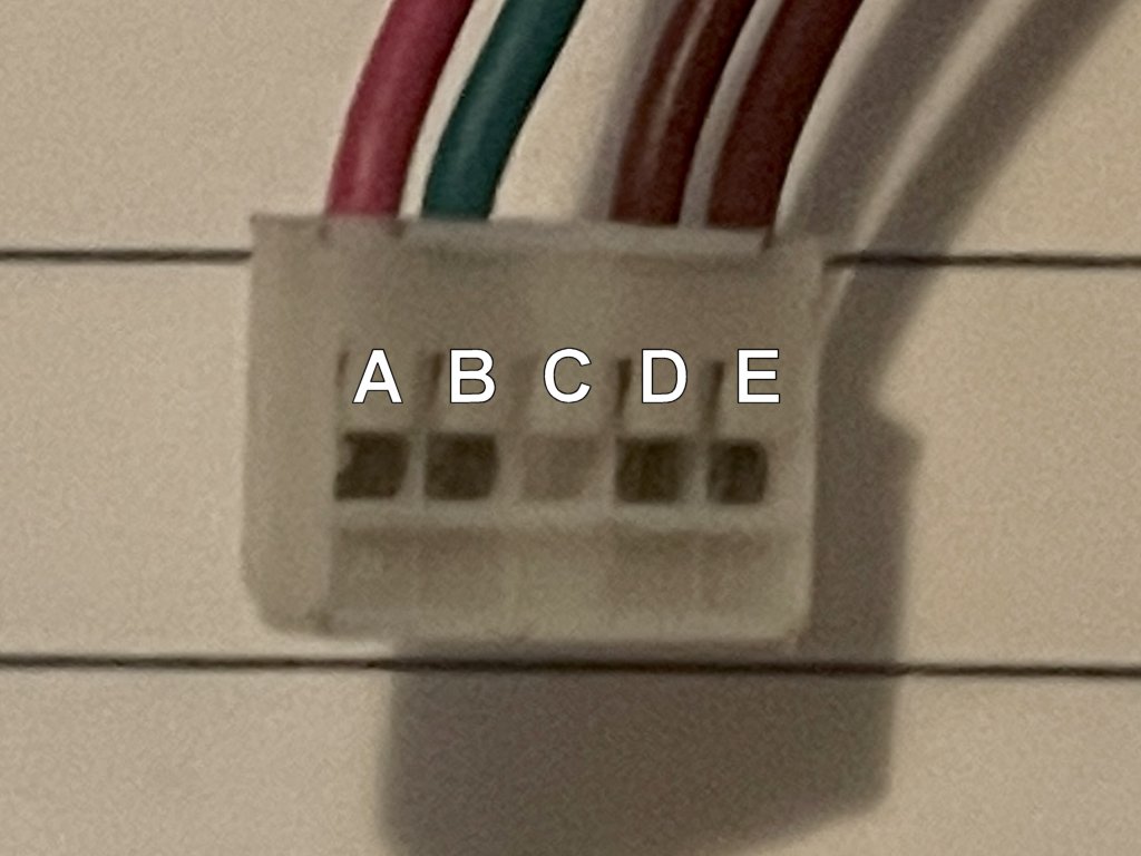
The “original” switch for this speed controller has two distinct states; when it is depressed the unit is on, when it returns it is off. I believe it is a Toowei 4000 series switch, and tests to be latching if put across another circuit. Picture and plug attached, yellow tape marks the positive signal wire:


The switch on the case appears to be a generic “clicky” push button momentary switch (Pictured previously in my current circuit). It is only completing the circuit when it is depressed, and in its original function I believe it’s latching was done in the original device. This is the switch I am trying to get to function with this newer speed controller.

Using the pins from the toowei switch, identified in the labels above (speed controller board doesn’t label these pins, hence my “ABCDE” nomlacture), if I connect my multimetre to each combination of pins on the speed controller I get the following results: (Table updated due to comments in next post)
IMAGE REMOVED TO AVOID CONFUSION WITH INACCURATE MEASUREMENTS
Please see posts below

First major comment - seeing 37V readings from these pins makes me aware the Pololu unit I am currently using may not be capable for this solution, the MAX voltage is listed as 20V, though any of the larger Pololu boards may work as they are rated to 40V. Max battery charge is 42V, so open to guidance here.

In normal operation:
LED+ connects to Pin A
LED- connects to Pin B
Pin C has not been previously used by the original Toowei switch, but is an active pin on the speed controller.
Switch- connects to Pin D
Switch+ connects to Pin E

The combinations of +A-B,+A-C,+B-A,+B-C, (A&B being the LED pins) when the D=>E circuit latches these readings ‘go crazy’ fluctuating by around 1-3V. I do find this odd, though can explain why the LED “flashes” when this is connected?

Do these voltage readings identify a ground pin? Does this open any other possibilities (relay)? Unfortunately, just reverting to the ‘normal’ switch for this speed controller defeats the purpose of this project.

Again, apologies if this info is somewhat obvious - I am very fresh to this side of electronics. I appreciate the help.

2 Likes

Note that if the switch simply connects D and E together then the measurement of 13.1v is not possible when the switch is pressed . When the switch has connected these two points then there could be no voltage potential between them (beyond a few mv of switch resistance).

Either the measurment is wrong or the switch is not doing what you think it is. Before looking for other options you should figure out why there is this inconsistency in your description.

2 Likes

Hi Jeff, Thanks for the response. Yes, I clearly didnt understand this when measuring - I have re-tested and the voltage drops from 13.1V to 0V when the contacts latch.

I have updated the table:
IMAGE REMOVED TO AVOID CONFUSION WITH INACCURATE MEASUREMENTS
Please see posts below

3 Likes

Hi Matt
The reason for wanting to know what the “mystery” device is that it might indicate just what the brown wires are switching.

From the voltage tables it would appear the “device” (as you have pointed out contains a speed controller) with a nominal 36V supply. It also appears the brown wires are not switching the prime supply but some other circuit which in turn switches the device on. I am not sure and could make no diagnosis unless the voltages are measured to ground as these brown wires are still unknown WRT any other circuitry.

There is something wrong with these measurements. Consider the “ON” matrix. This shows 0V between D & E which is as expected as these contacts should be closed so surely C to D & E should be the same. Something a bit fishy there.

I thought pin C might be ground but not at all sure so ignore. What does !!! mean on your meter. Can you find out please.

The LEDs may be meant to flash, there is no way of knowing without more info about the Device. The fluctuations 1-3V would be the forward voltage drop across the LEDs and appear to fluctuate due to the way a DMM does things, which is too long winded to go into here you will have to do your own research into that one. It is possible the !!! signifies “over range” as even with an auto ranging meter it might not have time to follow he variations it sees. This highlights a comment I made in another post which basically says you need to some idea of the limitations and be reasonably able to interpret what you see on a test instrument.

This is all getting down to the fact you may be better off with mechanically closing contacts as a latching relay or switch as we are not absolutely sure at this stage EXACTLY what these brown wires do other than SOMEHOW switch this device on and off. To use a relay or any other electronic means you still have to have a GROUND or NEGATIVE SUPPLY connection.

Exactly what is the prime supply to this “device”. Surely you can identify the negative or ground side of that. No matter what, if you want to do something completely electronically you need to know a bit more about the function of these brown wires and if using a relay you will need that GROUND or NEGATIVE V connection.
Cheers Bob

1 Like

Hi Bob, Thanks.

It is highly possible, even probable that this main switch drives an “anti-spark switch” of sorts. This is very common for use with other variations of these speed controllers, and operates in a very similar way to my understanding. If so it would be internal to the speed controller, though I can not confirm this is the case. It is probably obvious by now it is over my head, but it would be very normal to see one of these in this application.

Going by the pin labelling in this example: Simple 12s Anti Spark Switch - MakerX
It is possible my “C” pin may in fact be a GND pin, if this is driving an antispark switch, as the pins reflect very similar.

Yes, the LED flashing is normal operation for this device.

Also yes. When I remeasured for Jeff I only re-checked the D&E connections. This table should be more correct, I have re-done all measurements. Please let me know if it still doesn’t look right, happy to re-test for accuracy.

The “!!!” was not a display, I used this to indicate the voltage would not stabilize on any number but varied from 0-~3V, i have since swapped this to “?”, but it still means the same. I understand it will always be confusing to represent this. These are the LED pins, so it made sense to me that this may be a varied signal due to the flashing nature.

The prime supply is a 36V (42V Fully charged) battery. Yes, the posive and negative is easily visible on this battery deans connector, but a switched BMS (switched via the speed controller) affects the output voltage on these terminals. When the speed controller is “OFF” (and thus BMS), I read ~2-3V from the deans connector on the battery. Switch the speed controller “ON” (using original latching switch), and this voltage jumps to the full 40.5V. No connections change to read this difference.

I am open to options that don’t use the Pololu unit, but the significant part of the design is to maintain the ‘clicky’ push button switch. I cannot swap this element out.

Thanks again

1 Like

There is no obvious ‘ground’ from that table. But note that you do not necessarily need a ground in the literal meaning of that term. What you need is the zero voltage level for the D/E link. The latching module is electrically separate from any other part of the device, so what you use as ‘ground’ for the module does not necessarily have to be ‘ground’ for the device
 If you can find the zero voltage reference for the D/E pins then the D connection goes to VIn+ on the latching module and VOut+ is the E connection. That is, E will be connected to D when the module latches, otherwise E will not be connected to anything. The module is powered by the voltage between VIn+ and VIn-. The zero voltage that you find is then VIn- and VOut-.

I suspect that what you are reading as 13.1v is actually the nominal 12v supply, and that the zero voltage reference for that supply might actually be the device ground, but you would need to verify that.

3 Likes