Not sure what you are referring to as ‘no futher intervention’ but the GPIO output is connected directly to the amplifier input, so nothing else is required at that point. The process of setting up the MCU to generate PWM Audio is complex and shifting it to that other example he has come across would likely be very difficult. But he has it working already on the Pi Zero - that’s how he knows it is crackly.
1 Like
Hi Jeff
The Adafruit article on this product states that the input is AUDIO, NOT PWM.It even has provision for BALANCED audio connection which you change to UNBALANCED simply by connecting “A-” to ground.
Now can someone explain to me how you get an analog AUDIO signal directly out of a digital GPIO pin. I agree with the right sort of high frequency PWM and FILTERING an audio signal can be extracted. BUT, I don’t see any attempt at any filtering here or any mention of it. So if all these rectangular signals are being fed into an audio amplifier in their raw state I am not surprised at the result. Not to mention of course that if this PWM is at 5V (or even 3.3V would be marginal) the severe overloading that would be occurring for an input probably designed for line level inputs.
Or maybe that is how the Simpsons are meant to sound. Has anyone thought of that.
Cheers Bob
EDIT
The “no intervention” is meant to mean Joseph does not want to do any coding or in fact he just wants it to work which is understandable.
1 Like
The process is explained in the project description and in my comments above. There are many examples of PWM being used to create an analog signal. High frequency is important (which I mentioned) but filtering can be dispensed with if you aren’t too concerned about the quality which, as I suggested in my first reply, might be the case for this project.
3 Likes
Hi Bob
I’m having the same issue with the same project, and I can’t thank you enough for this rewiring fix! The audio is 90% better, just a high pitched noise I’m hoping to build a filter to fix next week.
Thanks again!
Martina
1 Like
SOLVED!
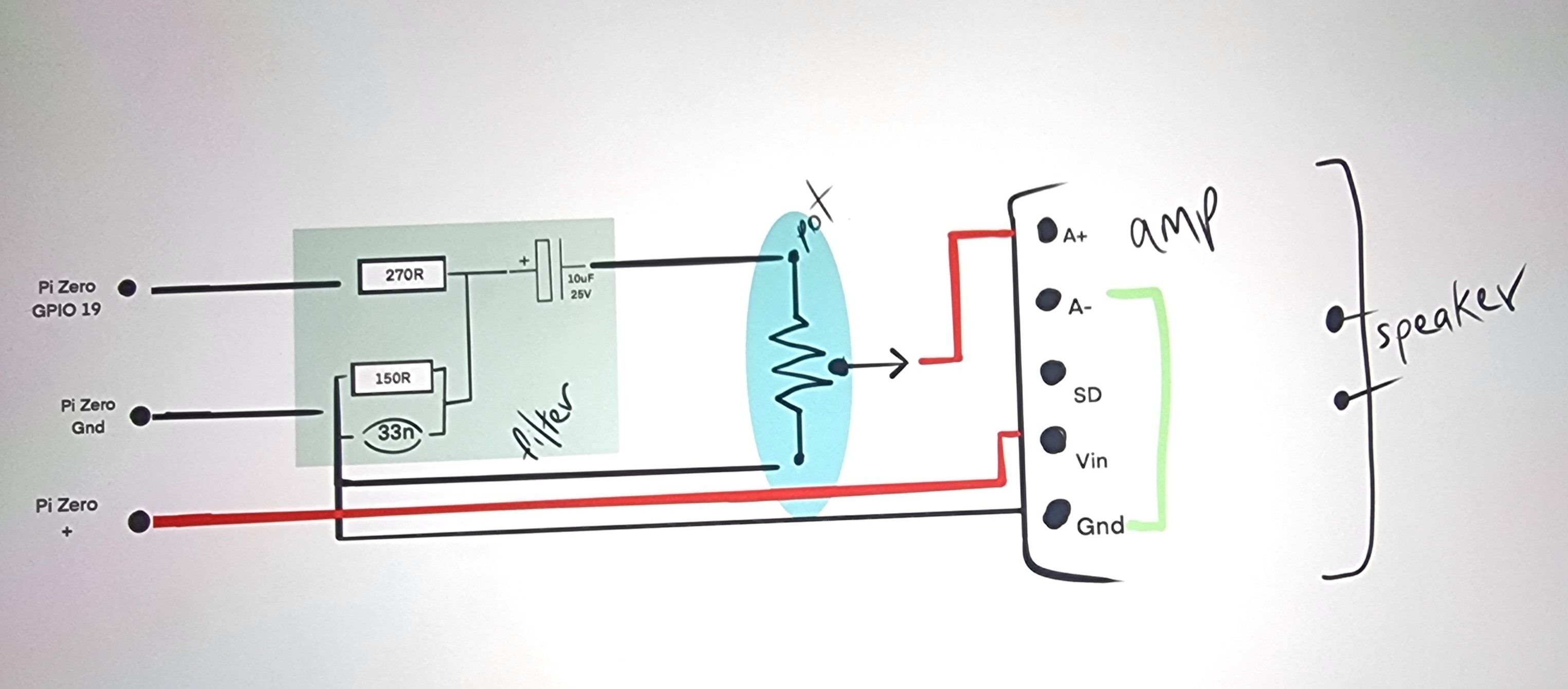
Thanks heaps to everyone that was involved in this fix. Using the rewiring suggested here by Bob and a filter suggested by Sudomod.com, using yet ANOTHER rewire by Adafruit themselves, this setup works perfectly with all the parts listed.
Thanks again!
1 Like
Hey @Martina285491,
That’s awesome! Glad to hear you got this figured out and working well. ![]()
1 Like
Any word on the spec of potentiometer you’ve used in this ? thanks
1 Like
Some time ago (Mar 2024) I replied to Joseph
I don’t know what Martina ended up using but for best results with audio this should be a logarithmic or curve “A”. Sometimes called “Audio Log”. 10k value should be OK.
Cheers Bob
2 Likes
Thanks for your help, Bob - really appreciate it. If you were going to build the same schematic, are there any changes you’d make to the filter block?
1 Like
Hi David
Before I commented on that I would simulate it and see just what it does. Seems to be a bit of a combination attenuator and low pass filter. the attenuator part might be advisable as this amp I think has quite a lot of gain.
Martina seemed to be happy with it so I would give this a go first. I have not got the bits to build it up to have a listen so I would be guessing.
Cheers Bob
Will try simulation when I get a chance.
1 Like