If you need more speed than the uno without increasing the cost, then checkout this board here.
Runs at 32MHz
12 bit ADC and DAC
Pin compatible with the uno
If you need more speed than the uno without increasing the cost, then checkout this board here.
Runs at 32MHz
12 bit ADC and DAC
Pin compatible with the uno
Can anyone assist in making this to install into my 66 Mustang so I have horse sounds PLEASE what parts where from how to assemble see:- https://www.youtube.com/watch?v=smhMLsP5fsM
This is the board used in the YouTube video. Suggest this as a starting point.
The audio output should be able to drive a small speaker for testing purposes.
NOTE: this device should only be powered from a 5VDC source, such as the USB port available in most cars nowadays. The video shows use of a 12VDC cigarette lighter connector and a voltage converter which you will most likely need in your 66 Mustang.
The other main part is an Audio Power Amp which drives the Horn speaker. These items could be sourced from a car audio shop, or they could advise you on what you need for your car and possibly install an amp and horn.
I would NOT solder large wires to the board as done in the video, I would use a header plug. The wires do not need to be that large. This is a similar device and shows much smaller wires.
Anyway, a good project.
Cheers
Jim
Hello James46717, This project and your comments have been really helpful!
I tried to use your code to record sound from a MAX4466 Electret amplifier and an arduino Nano. I have the microphone connected to ADC pin 2, and I’m powering the microphone from the nano’s 3v3 pin. I set ADMUX = 0x62.
I manage to record sound, but there is a loud background noise that sounds almost like clicking, with a frequency of roughly 30Hz. I’ve tried powering the nano from a battery instead of a power supply, but the sound persists. I tried setting setting REFS1,0 = 11 to use the internal Vref as well but this didn’t work.? After reading about some comments online, I think the problem may just be that the MAX4466 has lots of noise at low frequencies and I should try a different op amp. Do you have any suggestions for me? If not, I think I will give up on the MAX4466…
Hi Frank,
Glad you have found my project helpful. I have not used the MAX4466.
I cannot remember why I choose the MAX9814. But reviewing my project I think it is related to the fixed 2VPP output with 1.25V bias. Using a 2.5V reference means the signal at the micro pin is between 0.25V & 2.25V. This reduces the number of available samples but means the signal will not swing beyond the range of the ADC.
Faced with the problem you are experiencing …
Try the MAX4466 direct to ear plug headphones, like what you get with a mobile phone. Usually they are high impedance and should produce some sound even at low level. This is what I used in developing my project.
I assume you have been able to record the sound. Use Audacity to check how the audio looks. It might give some clues as to what is happening. Clipping of an audio signal can produce some weird effects. Probably you have already done this.
Try the circuit with a MAX9814, it may just be the MAX446 that is not working correctly.
I note:
Nano works of a 5V supply.
3.3V is generated by the FT232R chip and limited to 50mA.
MAX4466 powered from the 3.3V pin on the Nano; audio swing from 0 to 3.3V, offset bias 1.65V.
ADMUX = 0x62, ADC uses Vcc as reference, 0 to 5V with 2.5V mid point.
(nano does not have seperate AVcc pin available, Vcc & AVcc are connected together)
Maybe you could try powering the MAX4466 from 5V, that would put the bias point at 2.5V.
When I was developing the project, bias other than mid point of the ADC produced some strange results. If I remember right the effect you describe I did experience.
Anyway, all the best
Cheers
Jim
Hi Jim,
Thanks a lot for your detailed reply and suggestions!
I spent a bunch of time to day trying out different ways of adjusting the AREF voltage. I managed to get a somewhat cleaner signal by using a battery pack to drive the mic and another to set the AREF using an external voltage but I still haven’t completely figured out how to apply this voltage correctly. It does seem like the signal is cleaner when it’s oscillating around the 0 axis on the wav file. I need to think about it some more. I tried your suggestion of driving the mic using a 5V output from an Uno but it seems like certain low-frequency fluctuations in the voltage get amplified by the microphone. I’m going to set this problem aside for a few days and see if I can understand it better with a clear head in a few days. Maybe I just need to get a different mic+amplifier as you suggest… I wanted something that had a high sensitivity because I want to pick up changes in relatively faint sounds from a ventilation system that won’t be right next to the microphone. Maybe I need to invest in something more sophisticated for that… Thanks again for your advice! 
Best regards
Frank
Hey James. Great project. I am going to try this over the weekend.
What software are you using to draw the circuit diagram?
The circuit diagram was created with Tiny CAD. An excellent circuit drawing program.
Cheers
Jim
Hi James,
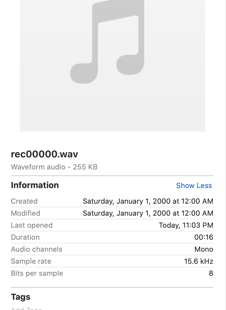
This is such a well-documented project. Thank you very much! But I am not able to get a successful recording. So I am doing a school project right now. I need to record audio with Arduino. I actually need to record for a few minutes and then play it back when I press a button. I first tried your code of the recording part. I did simple testing and successfully had the recorded wav file saved in my sd card. I have attached the screenshot of the file here. However, there is no sound other than the sound of two clicks.
Hi,
My development was done on a Windows 10 PC.
HxD allowed checking of the file, the micro was creating and comparing it to a real .wav file. This ensured the micro was creating the file correctly. HxD shows the bytes that make up a file. In your case it might not help.
Of more use would be Audacity, it has a Mac version that should work for you. The attached Audacity screenshot is a file recorded by the device. What ever audio you record should look like the pic, varying around 0 with a reasonable amplitude.
The micro is very busy when recording, the timing is critical, debugging can be hard as you cannot stop to send something to the serial port. Turning a LED on and off allowed indication of where it was in the code.
The code uses 2 buffers (256 bytes each), one to store the ADC data, the other is written to the SD card. The buffers are swapped when the ADC one becomes full. The SD card is a Class 10 (C10) 10MB/s. There is more than enough time for the SD card to write 256 bytes even on a Class 4 (C4) 4MB/s so that should not be a problem.
Hope you can solve the recording problem and thanks for your comments.
Regards
Jim
Hi James,
Excellent project. Thanks! for sharing ! I downloaded your sketch and succesfully compiled.
I am a radio amateur, and trying to use for a parrot repeater to connect to a transmiter/receiver.
Will appreciate to know if you thing the arduino 328 chip could be used with 3.3v, as that is the voltage available on the handy (I will use a Baofeng UV-5), as there are also SD card readers for arduino that also can work with 3.3v.
I was wondering if to store voice, instead of an SD Card, can be used a cheap serial flash memory, like the 25V32 (32 Mbit) that seems to be able to work in arduino, so as to avoid usage of an SD.
Thanks for any answer
Best regards, Pedro
Hi Pedro,
The datasheet for the ATMega328P lists 1.8 to 5.5V as the operating voltage. So it should work at 3V3.
The SD card was the easy option for me and allowed audio files to be easily removed from the device and with a large storage capacity.
Flash Memory should work as there is an Arduino Serial Flash library that treats the memory as a file system. Something like Adafruit SPI Serial flash SD card should work easily enough or
Adafruit SPI Flash SD Card - XTSD 512 MB | ADA4899 | Core Electronics Australia
Cheers
Jim
can you use the Micro SD TF Card Memory Shield Module instead of the “SparkFun Level Shifting microSD Breakout”? and how do you connect it then? (IO, DO, SCK)
https://electropeak.com/micro-sd-tf-card-adapter-module, the Micro SD TF dont work with this code
Hi @Emil208712,
This is the recording device I used for my project.
This is the card I am using. SanDisk Ultra 16GB Micro SD HC1 (10)
Previous posts by YU91678 show they were successful using the ‘SparkFun Level Shifting microSD Breakout’.
My code uses assembler references to achieve the speed needed to digitise and then the record the audio data. Timing is very important. There is a limited time for transfer of data to the SD card. I did extensive testing on this to ensure there was time to record the audio data by the card before the next data was ready.
The code uses 2 buffers one gets the audio data, the other is being written to the SD card. When writing is complete and the first buffer is full they are swapped. This was the only way for it to work within the time constraints. The size of the buffers is limited by the size of ATMega328P memory.
I would suggest getting the ‘Micro SD TF Card Memory Shield Module’ working using standard Arduino SD card libraries. This would prove the card works and the libraries work. You could also do some testing on how long reading & writing a file takes. If you have already done this, apologies.
The ‘Micro SD TF Card Memory Shield Module’ or the Micro SD card you are using might not be fast enough to record the data properly.
If you can provide more information as what you mean by
I may be able to help you further.
Regards
Jim
Thanks for your fast reply! what i meant with “the Micro SD TF dont work with this code” is that the card fails to Initialize. se attachment, thanks.
Thanks for the pic, shows where the error is.
The library is trying to initialise the card and the SPI interface for use and it is not getting the right response from the card. It try’s once and gives up, this happens very soon after power up. If the card is a little slower it may not be ready. You could try a delay loop before this statement, or a for loop to try a few times before giving up.
sd.begin(SD_CS, SPI_FULL_SPEED)
SD_CS is Digital pin 10 on the ATMega328P and enables the card. As far as I can tell looking at the circuit board pics and the datasheets this should work the same on both cards. It goes to the same pin of the SD card socket and through a non inverting buffer that can handle a wide range of input voltages. Note Digital pin 10 is Physical pin 16 on the ATMega328P.
SPI_FULL_SPEED tells the SPI interface to run as fast as it can, usually 8MHz.
But when I checked it now the variable SPI_FULL_SPEED = 50000000. Unsure if this makes any difference.
The other thing that has got me a number of times is the orientation of the MISO & MOSI lines.
Kick myself when I realise I had them around the wrong way.
I assume you have formatted the micro SD card as Fat32 before trying to use it, NTFS or exFat will not work with the library. The library I used at the time of the project was Version 1.0.7, you could try reverting to that library, it might work.
Try some of the examples that come with the SDFat library to confirm the card and the library.
Unsure what else to suggest.
Regards
Jim
And you can get our latest projects and tips straight away by following us on:
![]()
![]()
![]()
![]()