I have just shared a new project: “The Rats Nest VCC Desktop Power Supply”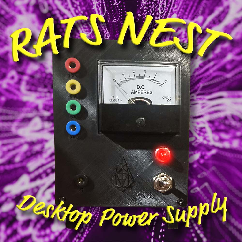
Cute & Easy Desktop Power Supply for Casuals.No matter what I do, every single time I want to make a circuit, it needs power! Gracious!
Instead of finding the right power supply from the draw, and some way of MacGyvering it to the right connect…
Read more
2 Likes
Hi Pix
Good project and a very useful device.
Some constructive (I hope) comments
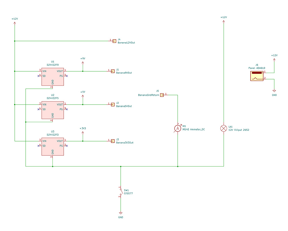
Where do you physically connect your “my circuit” ground. It is a bit hard to see but it looks like there is a black socket on the front panel. If this is it and it is the black symbol marked “ground” on the schematic then the switch and meter will not be in circuit but active all the time. If you want to be able to switch power OFF the simplest way would be to swap the switch and ground positions.
Or is there some way to connect “my circuit” ground to meter positive as in the schematic
While on this subject you do realise that the if used in this configuration with the “My circuit” ground connected to meter + it will be some mV above the terminal ground. This could result in some problems if you have a ground conflict or phantom connection somewhere. Possibilities are through the mains ground via test equipment grounds and the like. The plug pack 12V source should be isolated from “Ground” so you should be OK. Just be aware of the condition and be careful. Take into consideration that little bit of resistance of the meter between the DUT negative and supply negative if you get any unexpected results for any reason.
Thinking about longevity and reliability. In my book the devices such as this should be pretty much beyond reproach and should be extremely reliable. Nothing like finding a fault your bench equipment has put there unknowingly.
I hope those breadboards are classified as “my circuit” and not part of a permanent system. I am not a fan of using these in a permanent situation. They are designed as an experimental tool and I don’t think the contact material would be considered in any way suitable for “Permanent use”. I stress this is only my opinion.
Those terminal blocks you used. These should be fitted with “wire protectors” or if bare screws the wires should have bootlace ferrules fitted. Bare screws WILL damage the wire and will result in unreliable connections. The last thing you need in a device used for testing.
Don’t be frightened to solder. Consider every friction contact that is not really need is anotherr potential source of a problem and in a part of a test set up this should be minimised. As it is DC if you have a need to get the panel clear for internal access just form the wires up neatly and leave them long enough for reasonable access. I see you have used crimp spade push on type terminals on the front panel plugs. What sort of crimp tool did you use? Does not look like the right one from here, the insulation support bit of the crimp has not been crimped. I suggest you solder these for the above reasons and if you do you can get rid of that terminal block while you are at it. Or if you think you might need complete panel removing at some tome you can leave it there with the cautions outlined above re bootlace ferrules.
Cheers Bob
1 Like
I think you might be looking at the flow diagram at the beginning of the write up.
You will prefer the official schematic at the end. The black GND banana plug return, the meter, and the switch, are all in series.
In my head this entire power supply is just a glorified version of this. Like add on a few regulator and your basically there.
A good improvement. Next time I open this up I’ll make the change.
This project actually taught me the value of a real set of crimps.
I used a strong set of pliers which sucked.
I recommended a good set of crimps in the BOM and bought one for myself.
I think I see what you’re asking.
This power supply is not pro grade equipment and shouldn’t be used as such. It’s just an easy way to get very quick power for beginner maker projects. Any breadboards depicted are examples of the use cases I’m imagining, not part of the power supply.
e.g. Here is an alternative pic with some jellybean parts to give you a better idea.
The power supply is just providing 3V3, “my circuit” is a stand in for whatever it is you want to power, in this case it’s a diode, cap, led and resistor.

Hi Pix
Thanks for the reply.
Cleared up things somewhat.
Yes I was
Yes I do BUT !! this was not there a couple of hours ago for some reason.Stranger things have happened I suppose. The word “Schematic” was there but nothing else.
Comments about the grounds have not changed. The DUT ground will be some mV different from the input supply ground (-12V).
Good idea. But the wire protected type of terminal block might be a bit difficult. I don’t recollect ever seeing them in Core stock and I haven’t seen them at Jaycar for some time now so until I find a supplier I have been using Bootlace ferrules. Some time ago I purchased a kit for not too many dollars. Several hundred ferrules over 8 sizes complete with a Wago style crimp tool. No brand but marked HSC86-4 and covers 7 - 23AWG or 0.25 - 10 sqmm. I am pretty happy with it so far.
Good
Naughty but you have evidently learned
True but there is nothing wrong with making it as reliable as you can. It is not even any sort of power “supply”. It is only manipulating what is provided by the real supply for easy and convenient use. As such a very worthwhile addition to your work space.
I was hoping and expecting you to say that.
As for conflicting grounds. If you have any trouble here just reposition the meter to the 12V input line to the regulators and 12V output. There are no active electronics involved so it does not matter where it goes. The practise of locating a meter in the -ve line arises where there is a display with active electronics and is powered from the supply input. Does not apply here.
Down side is it will read the idle current used by the regulators even if no outputs used. This might only be a couple of mA and might not even deflect a 5A meter. The ON/OFF switch could even be moved if this is a concern
Cheers Bob
1 Like