It looks like you’ve missed counting 2 gears - there’ll be small gears underneath your gears 4 & 5. These are Double Reduction Gears - they are similar to the one driving the final output shaft, but they are inverted. They are fixed together just like the blue and yellow gears below:
I’ll work through the calculation as if what you had counted is correct so you can see process anyway, even though the result will be wrong - and it’ll show the need for the double reduction gears vs idler gears.
Calculating gear ratios is simple multiplication and division.
Starting from gear 1:
Gear 1 teeth / Gear 2 teeth = Gear Ratio 1 24 / 9 = 2.666...
Gear 2 and 3 are stuck together on the same shaft - they are forced to spin at the same speed so: Ratio 2 = 1
Then the gear ratio for the whole gear train is:
Ratio 1 x Ratio 2 x Ratio 3 x Ratio 4 = Gear Train Ratio 2.666... x 1 x 1.185185... x 1.22727272... ~= 3.89
An interesting thing to note as that without double reduction gears every gear in the middle cancels out as an idler gear - the only thing these do is reverse the direction of rotation. You can show this mathematically by looking at the contribution of Gears 3, 4, and 5:
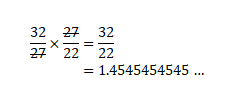
Ratio 3 x Ratio 4 1.185185185... x 1.2272727272... = 1.45454545...
As you can see in this incorrect case, Gear 4 makes no contribution to the gear ratio, and the ratio we calculated of 3.89:1 is well off the mark of the actual ratio of ~16:1
I have recounted the inner and outer teeth on all of the cogs again and below is a summary of each cog starting from the cog with the shaft and then the connecting cogs going in a clockwise direction as per the image i sent previously above.
Great, perfect timing - moments after I posted above
=> For every 1 turn of the output shaft, the input shaft will turn 64 times.
If those gear tooth counts are correct it’s a 64:1 gear train! Either we’re missing a set of gears that make a 4:1 ratio, or it is indeed a 64:1 gearbox.
I have recounted the teeth again and they are correct and I haven’t missed any hidden cogs either…
You have mathematically proven that it looks like 64 is the correct magical number.
Thanks for satisfying my curiosity and the least I have learnt heaps in the past 24 hours…
Hopefully the current motor goes for a good length of time again and when it stops at least I have a starting point knowledge and confident enough to dismantle it and “do my maths on the gear ratio” and contact you guys to help finding a replacement.
Did a bit of a search yesterday on part number 28BYJ-48. Seems most parts are 64:1 gear boxes but some are 16:1 with the same part number. Confusing what???. There are a couple of switching sequence charts presented which I think are half stepping (64ppr) making this configuration overall 4096 ppr of the final shaft.
Cheers Bob
This has been a fascinating read, learnt much from everyone who has posted here.
You measured 60 steps in 1 minute equalling 1 per second. Anything you replace it with would need to do the same. Regardless of gear ratios or steps per revolution. But if you are using the original circuit board you would need to find a 44 steps per revolution motor or the timing would be out. Have never seen a 44 steps per revolution motor. Probably they had the motors specially made
Finding this out is a nice achievement. It means the timing is related to every second. The globe would keep pace with the actual rotation of the Earth. Remembering it takes slightly less than 24 hours to rotate. (23 hours, 56 minutes and 4.09053 seconds) So it would eventually need adjustment.
After some thought I have it WRONG in my original post.
Oliver is correct. Apologies for adding some confusion.
Having the gear ratios of each side makes it easier to understand and calculate. (Multiplying and not Adding, Jim, get it right) Took a while to sink in.
Making 64:1 and 16:1 motors with same number is very confusing.
What is evident to me now is that this motor is most likely irreplaceable and I’m just crossing my fingers that it keeps going for as long as possible!!!
I’ve also decided that in order to prolong it’s lifespan I’m going to regularly switch off the globe and give the motor a good rest.
Not quite correct. The end result is 44 steps per rev of the shaft. The actual stepper movement would be this movement multiplied by the gear box ratio.
Refer Peters video. The shaft moves 48 distinct steps per rev. 1 step per sec.
44 steps per rev = 8.182º per step. Now every second the stepper has to move 8.182º X gearbox ratio. Now what I think happens here is that exactly every second the stepper is driven with enough steps to achieve this. In other words the actual stepper is operating in little bursts at 1 second intervals to achieve the 44 distinct steps per rev of the final shaft. You can see there is a lot more info needed to determine how many steps per rev is the actual requirement of the motor. You would also need to know (or measure) how many step pulses are used in each of these bursts. This would be determined by the operating software and would be very difficult to change.
So I hope Peter’s stepper runs for a long time yet.
There is one thought. I doubt the manufacturers would go to the expense of having a special one off stepper made. There are other similar devices around so it is possible the driving electronics are the same. Maybe worth a search for info.
May be quite wrong here. Please correct if this is so.
Cheers Bob
Hi Bob, I emailed the manufacturer a few times asking for their help and the replies I got from them was " sorry this product has been discontinued and we can’t help you…"
I was lucky enough to stumble on this forum to get this invaluable help and knowledge
Sorry to post here again after the problem seems to have resolved itself. (how many times have you done that to me electronics, lol) But I like to understand exactly what is happening, when I do it all makes sense.
I watched video and counted the number of pulses, 53, and note that the video length is 53 seconds.
I also note that Y1 32768HZ is a standard watch crystal.
And Peter stated it did 60 steps in 1 minute.
The motor is moving the large gears inside the globe at 1 second intervals.
Is it possible this circuit is a simple oscillator providing a pulse to the motor every second to move it one step ??
The reason why I made the video 53 seconds is because I wanted to ensure that the shaft was exactly on the 12 position to make it easier for me to start the count and I could also double check the count.
You may have misread this, easy to do. It seemed to me that this is a big difference and it would not take long to gain or lose a day @ almost 4 min per day.
Trusty google says Earth rotates once in about 24 hours with respect to the Sun, but once every 23 hours, 56 minutes, and 4 seconds with respect to other, distant, stars
It is WRT our sun which is of interest to us earthlings.
That crystal is indeed a clock frequency. Probably to provide an accurate one sec “tick” to trigger the stepper driver circuitry to do it’s thing. I suspect there are lots of other bits including the odd IC on the other side of that board.
Would not matter what the focus is like. I would not even think about trying to work out what is happening there without a circuit and explanation. That board could well be multi layer which means it is made up of several layers sandwiched together each layer has tracks on it which at the end of the day you can’t see. I would get a working board, observe what is happening and when with an oscilloscope and take their word for it. That big IC could be a unique device which for the likes of us pretty much unobtainable. Doorstop???
Cheers Bob