I bought a sim7000E module Link , I was tried to connect the sim7000e module to the local network but i cant connect to any network. i used Vodafone, belong and boost sim, no any luck yet, i need to know is this support to Australia networks ?? thank you
It supports bands 3, 8, 20, and 28. Band 28 is the main 4G band in Australia so it will work as long as it’s configured correctly and you’ve got coverage.
What’s your configuration?
i just connect the GSM antenna and insert the Sim card and connect the device to pc using micro USB cable, then I used the AT command tool and install the correct drivers. and I refer the user manual and i wait till to register to network but i cant connect. this is the led indicator details
and still its flashing one time per second
I’d be very surprised if it can just automagically connect. I suspect you’ll need to set up your apn etc.
Hey Chamika,
I would also double check that you have a good connection to the towers i.e. outside or near a window facing a local phone tower.
Other users had some luck in getting the boards to connect straight away from other countries, I’d check out this guide here(uses the same sim7000e chip) to make sure your board is running correctly: 4G Hat - Raspberry Pi Forums
I’m sure the guys over at Core are doing some testing to get back to you with some more info.
Liam.
Hey Chamika,
We’ve got the board here from stock at the moment in the workshop, it should be compatible with Australian networks although I expect that you’ll need to do some configuration first before it functions correctly within your project. We’re currently looking into the setup for you and will get back to you soon. Have a great day!
1 Like
Have a look at this
Looks like it’s actually for the SIM7600E, but there might still be some overlap.
1 Like
Hey Chamika,
We’ve been having a look into this one today but have hit a roadblock as the documentation on the SIM7000E is a bit of a rabbit hole. We’ll get back to you if we can manage to find a more detailed answer on this.
Like with all products, the best support comes from the OEM so if possible I’d suggest getting in contact with SimCom, you can send them a question via their support portal here.
Your troubles have encouraged me to pull out my SIM7000E Shield for my Arduino. I bought it ages ago when they were on clearance, but hadn’t even taken it out of the packet until now!
Here’s a really great thread from a while back:
Here’s what I’ve learned so far:
- The SIM7000E is certified by Telstra, so no issues there. It definitely works in Aus, and others have gotten them working.

Your path of least resistance will be to get an IoT SIM from Telstra or Hologram:
IoT Data SIM plans
Hologram Hyper - eUICC Global IoT SIM Card | Core Electronics Australia - DFRobot’s SIM7000E library will only work with NB-IoT - you’d need to modify that to get it to work with a normal SIM on CAT M1.
- I’m using my phone SIM to test, which is on the Optus network (via Dodo)- where I live there doesn’t seem to be any Optus band 3 or 28, so haven’t gotten it working yet. I can see Telstra and RailCorp though!
- This is a handy guide to using AT Commands (PS. AT Commands are specified by the 3GPP, but manufacturers have additional ones of their own on top). Ublox also has a handy guide.

So far as I can tell, this should be the process to connect to a network using AT Commands, once you’ve established a UART connection (Note that the chip itself is a 1.8V logic level device if you’re planning on trying to bypass the rest of the circuitry and tie directly into the pins).
Choose a baudrate from:
- 9600,
- 19200,
- 38400,
- 57600,
- 115200
The SIM7000 modules support Auto baudrate detection - I think 115200 is the default. It can do other baudrates other than those listed above, but you need to establish a connection first and then configure it manually - get a list of supported baudrates with AT+IPR=?.
Make sure you’ve got carriage return and linefeeds ('\r\n') being appended to your serial inputs, then enter the following sequence of commands to get connected to a network.
AT //Response should be 'OK' - Test communication with the SIM7000E so it can automatically adjust its baudrate.
ATE1 //E for echo, 1 for on - Makes it Echo back the commands you send it, so the history makes a lot more sense on your serial monitor.
AT+CMEE=2 // Enable verbose error output
AT+CPIN? // Response should be READY - See if the the SIM7000 has recognised your SIM card. If you get a response other than READY or an error, your SIM is password protected.
AT+CNMP=38 //LTE mode only -  Preferred Network Mode; Other settings: 2 Automatic, 13 GSM Only, 51 LTE and GSM Only
AT+CMNB=1 //CAT M1 Mode - Other settings: 2 NB-IoT Mode, 3, both CAT M1 and NB-IoT.
AT+CSQ //Check Signal Quality/Strength: [0-31/99],[0-7/99] - Signal Strength 0=-115dBm to 31 >=-52dBm, Error Rate: 0 = <0.2% - 7 = > 12.8%. 99 is not detected/unknown.
AT+CREG=1 //Enable reporting on network registration status.
AT+CREG? // A good response is: 1,1 or 1,5 - we're registered on a network already!
AT+COPS=? //Search for available providers. Warning this command may take a couple of minutes to respond - it hasn't frozen just let it go.
At this point you’ll want to look up your provider’s code. See here:
If your module returns +COPS: (1,....... good news - that network where the first value is 1 is available for you to connect to! 3 means forbidden - eg. you have an Optus Sim, and that’s a Telstra network.
AT+CNBP? //Check which bands you have enabled (This command was removed in firmware version 1.05 so if you just get an error, you need to checkout the newer AT Command guide from SimCom)
AT+CNBP=0xFFFFFFFF7FFFFFFF,0x000007FF3FDF3FFF //Set it to use any bands available
AT+COPS=0 //Automatically select a network operator.
This is as far as I’ve gotten.
Update:
I was able to successfully update the firmware following the instructions here:

2 Likes
Oh and PS. Just posting this sketch in case its ever useful for anyone - I couldn’t find an example passthrough sketch with a buffer when I was searching, and you need it when you’ve got very different baudrates (and need to send a complete string, like with AT commands). It can obviously be simplified further, probably down to a single function or as basic library, but it’s simple enough for this.
These functions can be thrown in with other code - they’re written so they won’t hang your program waiting for serial data if there’s none available.
/*
  Software Serial Passthrough sketch - with a string buffer
  Written to pass AT commands to a shield via a software serial port.
  Based on https://forum.arduino.cc/t/serial-input-basics/278284
  Buffers until it hits a newline character '\n'
*/
#include <SoftwareSerial.h>


int const BufferLength = 64; //Set the maximum number of characters to buffer before printing
char SerialBuffer[BufferLength+1] = {0}; //Allocate the memmory. Don't forget to +1 for the end of string null byte.
char SoftSerialBuffer[BufferLength+1] = {0};
char rc;  //A received character
char const endMarker = '\n';  //our end of string marker
boolean PrintToSerial = false;  //Are we ready to transmit data received from the Software Serial port over the Hardware Serial port?
boolean PrintToSoftSerial = false; //Are we ready to transmit data received from the Hardware Serial port over the SoftwareSerial port?

SoftwareSerial SoftSerial(11, 10);

void setup() {
  Serial.begin(115200);
  SoftSerial.begin(300);
}

void loop() {
  ReadSerial();
  ReadSoftSerial();
  PrintData();
}

void ReadSerial() {
  static unsigned int BufferIndex = 0;

  while (Serial.available() > 0  && PrintToSoftSerial == false) {  // If anything comes in Hardware Serial (USB),
rc = Serial.read(); // Buffer the input.
SerialBuffer[BufferIndex] = rc;
BufferIndex++;

if (rc == endMarker || BufferIndex >= BufferLength) { //if we're at the the end, or run out of storage space
  //terminate the string and print
  SerialBuffer[BufferIndex] = '\0';
  BufferIndex = 0; //reset for the next string
  PrintToSoftSerial = true;
}
  }
}

void ReadSoftSerial() {
  static unsigned int SoftBufferIndex = 0;

  while (SoftSerial.available() > 0  && PrintToSerial == false) {  // If anything comes in the Software Serial port
rc = SoftSerial.read(); // Buffer the input.
SoftSerialBuffer[SoftBufferIndex] = rc;
SoftBufferIndex++;

if (rc == endMarker || SoftBufferIndex >= BufferLength) { //if we're at the the end, or run out of storage space
  //terminate the string and print
  SoftSerialBuffer[SoftBufferIndex] = '\0';
  SoftBufferIndex = 0; //reset for the next string
  PrintToSerial = true;
}
  }
}

void PrintData() {
  if (PrintToSerial == true) {
Serial.println(SoftSerialBuffer);  //Send data from SoftSerial over Hardware Serial
PrintToSerial = false;
  }
  if (PrintToSoftSerial == true) {
SoftSerial.print(SerialBuffer); //Send data from Hardware Serial over SoftwareSerial
PrintToSoftSerial = false;
  }
}
3 Likes
An addendum, I just discovered this excellent troubleshooting guide from Botletics:
2 Likes
Update - I bought myself a $2 pre-paid Telstra SIM - I’m connected!


I didn’t bother paying for any credit, so I can only receive, but I CAN receive! 
I’m connected via CAT-M1
PS: a fantastic plain English tutorial:
https://www.developershome.com/sms/howToUseHyperTerminal.asp
Understanding AT commands is hard - @Tim should write a tutorial 
2 Likes
Thank you so much ill try
2 Likes
Amazing work! Let me see what I can do 
3 Likes
Did you use an M2M (IoT) chip? only works with this type of chip? I have the same problem here.
Hi Luiz, Welcome to the Forum!
I’m not too familiar with the differences in M2M and IoT, and how they would come into play here, could you enlighten us?
-James
1 Like
I used a standard telstra SIM for this test (SMS), but the best solution would be a dedicated M2M/IoT SIM - either an NB-IoT SIM from telstra, or one of the Hologram IoT SIMs (core sell these, and they work internationally).
5 Likes
Hi All,
I’m in New Zealand at the moment and have terrible reception at my house, but I picked myself up the same Waveshare SIM7000E as @Chamika129631 and after installing the SIMCOM drivers for windows, have even been able to use this one as a 4G modem!
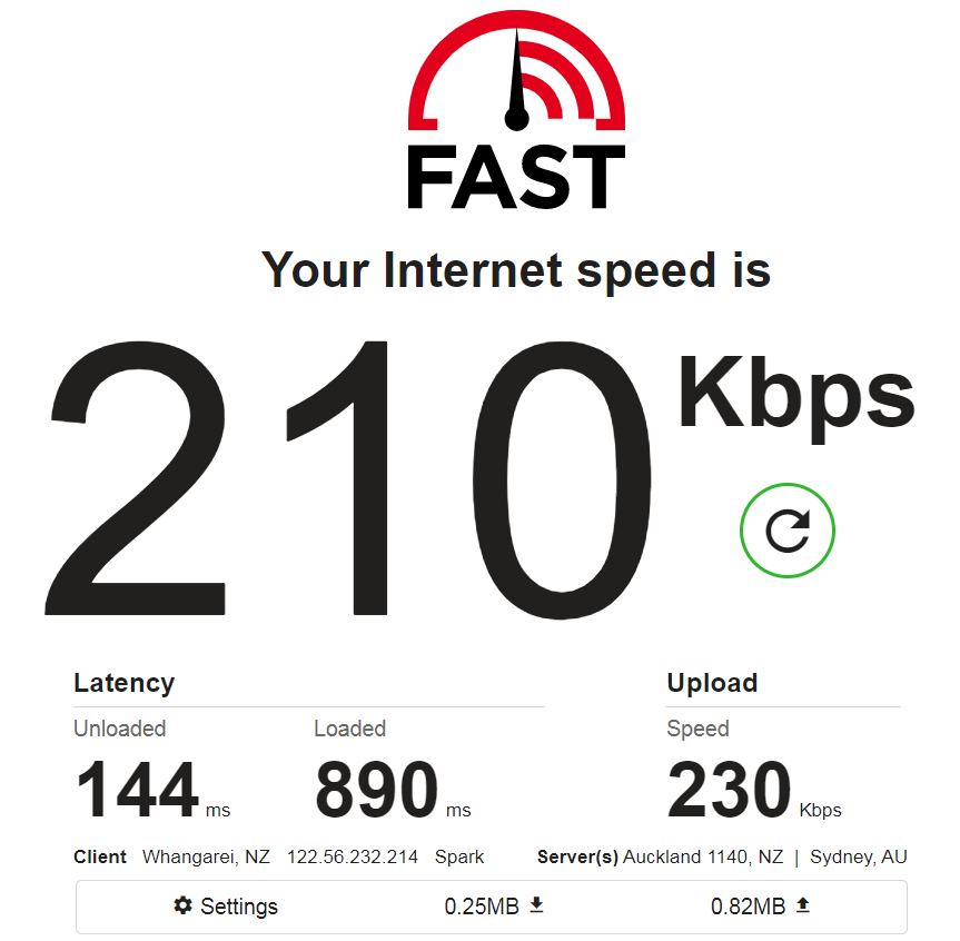

For reference, I’m on the Spark Network, and Skinny is my provider. Next step, getting this setup on a Raspberry Pi Zero 
4 Likes
Hi Oliver, thanks for your excellent post on this topic on getting the Sim7000e shield to register SIMs onto the 4G network. I followed and got my Telstra (and the Optus) SIM registered. However, when sending the SMS it is coming back with an CMS Error 500.
2 Likes