I’ve got a slow clock (< 1khz) and I want to invert that clock.
I’ve seen lot’s of way to do this with logic gates but I’ve done that before and I want to try something different.
How would you convert a clock signal?
Anything fun for me to explode… I mean explore.
Hi Bob, thanks for jumping in to help me again
It is a square wave with a roughly 50% duty cycle.
It’s really about shifting the phase.
Some of my components are Active LOW and other components are Active HIGH.
I’d like the same clock to control them both, so I just need a copy of that clock but inverted.
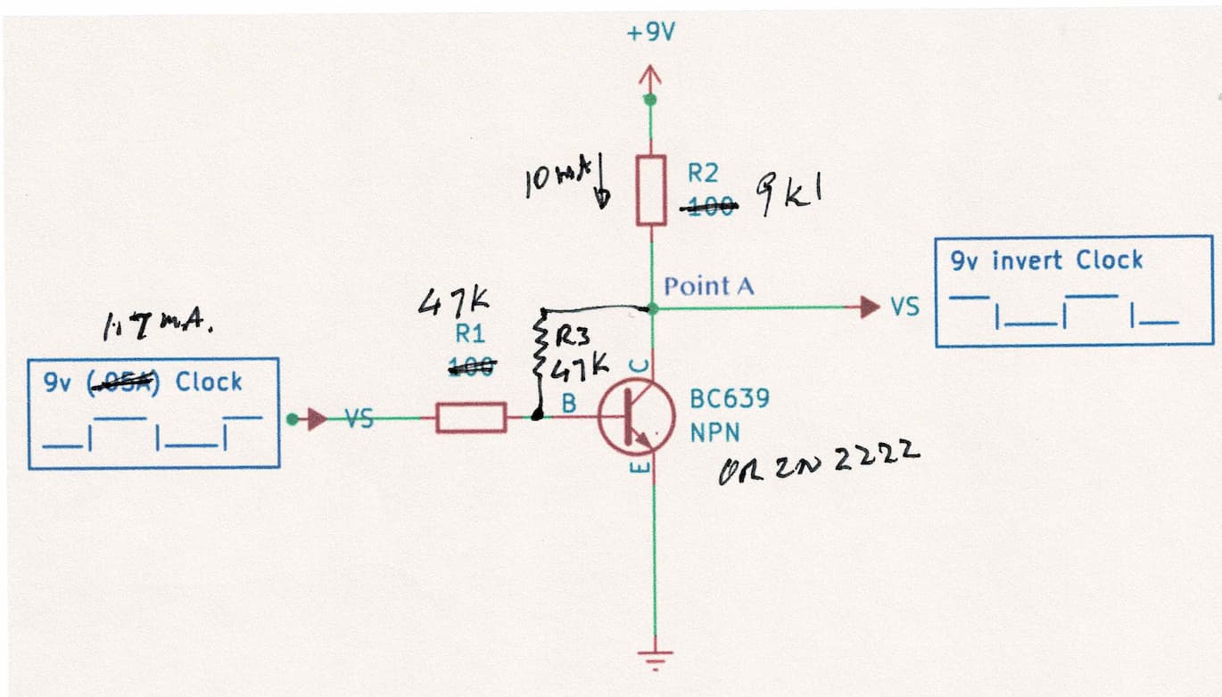
i.e. I need both the RED and BLUE signals in the picture below.
When the RED is HIGH the BLUE is LOW and vice versa.
Hi Pix
Only low frequency so that is easy.
The simplest way would be to use an inverting schmidt trigger such as a 74LS14. The down side is they usually come in a pack of 6 so you are left with 5 unused. The up side is no external components. One connection for IN and another for OUT. Also if you connect all the INs together you have 5 extra OUTs to do whatever you like. Of you want another in phase OUT just connect 2 sections in series to restore the original phase.
Second use an OP Amp. Configured for unity gain. Connect the + input to ground, connect the signal to - input via 10kΩ resistor, connect another 10kΩ from output back to - input.
Third use a suitable switching transistor such as 2N2222. Emitter to ground. Signal to base via resistor, value to set enough base current to turn transistor fully on. Collector to VCC via resistor, value to limit collector current to say half hormal current. Resistor EXACRLY the same value as series base resistor from collector to base. Unity gain, voltage inversion. You will have to look up the spec sheet for resistor values
Cheers Bob
I want to type out how I think this circuit works to see if I get it right.
In the scenario when the clock is LOW the transistor closes so current chooses to flow HIGH out to my inverted clock at POINT A. If the clock IN is LOW the clock OUT is HIGH.
In the scenario when the clock is HIGH the transistor opens and sinks current.
This GROUNDS my inverted clock at POINT A. If the clock IN is HIGH the clock OUT is LOW.
You left out R3.
Try with these values, they should work. You only need about 10mA collector current so 1.7mA base current should be plenty.
A 2N2222 might be a bit better transistor as the saturation voltage drop might be less so you will get your output a bit closer to ground. If you have a BC639 on hand by all means use it to prove the component values.
Cheers Bob
Hi Pix and All
Must have had a brain snap. R3 should be 910Ω or 1kΩ OK.
If the transistor does not not saturate decrease R1 but it is highly likely the clock source supplies volts with very little current. If it cannot supply the base current a higher resistance load is required which would be a different circuit or Op Amp.
R3 must be the same value as R1 to be a unity gain amplifier or to use the transistor as a switch leave it out.
Your analysis of the circuit operation is totally wrong. I will describe late when I have a bit more time.
Cheers Bob
Add on re transistor operation.
You are half correct, I think only terminology but you basically have the right idea.
Clock LOW the transistor turns OFF (I read “closes” as ON) and 9V is at point A.
Clock High the transistor is ON (I read “opens” as OFF) and if saturated will be almost a short to ground so should be almost 0V at point A.