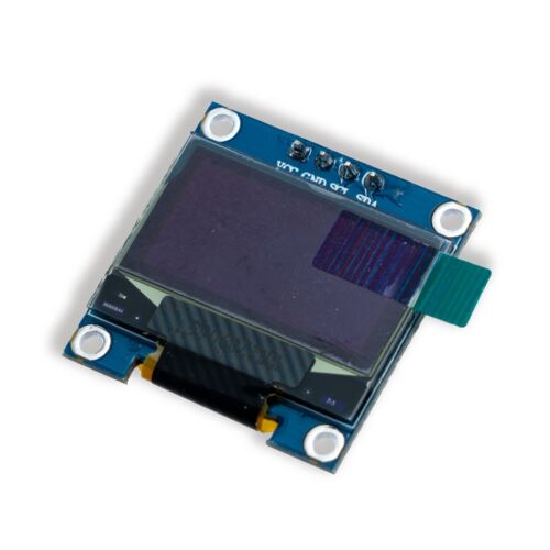
Looking for an OLED display to add to your DIY projects? Check out our White I2C OLED display with a 0.96-inch screen and 3.3V input compatibility. Easily print text and draw shapes with this go-to maker display using the SSD1306 driver.
Hi. How many I2C addresses are available on the SKU CEO9493 OLED display? This will be an existing addition to a RPI Pico / Circuitpython application. Will the available libraries support larger fonts? Thanks…
Best I can tell is its a 3.3V device. So you would need a 5V to 3.3V power regulator to supply the 3.3V to power it. Common ground to your controller, then a logic level shifter on the Data and Clock pins (5V on the high side, 3.3V on the lower side)
So I can see why the i2c would not work, just need the voltage levels adjusted with some bits in the middle.
yeah, I suspect that some data sheets talk about the chip itself while others talk about the “user interface”
I based my comment on the schematic link on the core page for that device, that only shows 3.3V
the Datasheet I looked at said +V was 7 - 15 V but logic was 3.3V. So 7- 15V was not even 5V, so I would guess that that unit has some sort of voltage regulator to drop down to what was needed.
Some display have a LDO that when supplied with 5V will drop down to 3.3V; then when supplied with 3.3V will drop down to about 3V, which is normally enough to power things. So they then say “3.3V or 5V”, but all the logic IO is all 3.3V
So play it safe and use the 3.3V as you would still need a 3.3V source to drive the logic level shifter.
I looked into this once for a micro-display i later abandoned.
To learn about that, you need to scroll aaaaaalllll the way down to the bottom of the datasheet.
In the ‘application note’ section you learn that the chip inside this oled: the SSD1306Z IC, has an honest to god built in charge pump.
I think the vision here is to permit the use of 1.5v button cell lithium batteries, perhaps target the wearable electronics crowd (a very Adafruit thing to do).
Additionally, the SSD1306Z, the chip specifically, can be paired with other panels.
Nerds sometimes use the SSD1306Z to build custom displays. That’s what the “7v - for pannel driving” is all about.
HOWEVER// TL;DR
Lovely as it is, the i2c bus still absolutely demands 3.3v logic level regardless of what’s happening @ VDD.
So if you’re starting at 5, you’ll need to fall to 3.3 at some point and the logic level shifter, as suggested by others, feels perfect. (or a mosfet… maybe?)
The Nano can provide up to 50mA from the 3.3V regulator that is part of the USB chip. It appears from the display data sheet that the current draw is well below that, so it is likely that the Nano 3.3V supply can power both the level converter and the display.
Clones that do not use the FT232R USB chip will have a different arrangement for the 3.3V supply, and the maximum load may be different.
Thanks everyone, been busy with my granddaughter who has just gone to sleep (sleep over). It’s not important enough for me to bother with any additional circuitry. I just have some of these in my store and hoped I could use it for the bytebeat noise maker. I do like visual feedback…
When I’m wanting some visual feedback for bytes I like to use an 8x8 led matrix and two shift registers. I use the 74HC595s.
Clock to the x axis (so each byte) and data on the y axis.
I punch the data coming out of the serial or PWM pin straight into the latches, (through a diode), and then I visualize the latches on the matrix. Super easy

