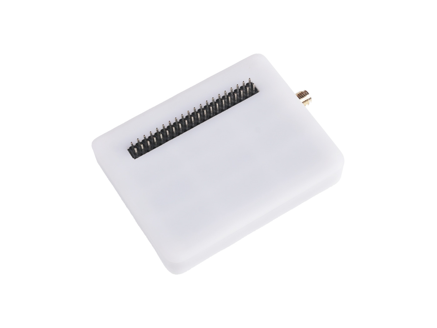
I have solved the problem I was experiencing with rebuilding the LoRa Tester firmware for AU915 CH 8-15 (as used by TTN in Australia).
Follow all the steps in the instructions to update your libraries. But, most importantly, do not forget to set the device to slave mode. This is needed because of a swap in the use of the Tx & Rx data lines. To do this, from the Arduino Menu select TOOLS / ROLE and then select SLAVE. If you don’t do this you will have TX-TX and RX-RX instead of TX-RX and RX-TX. This will then cause all AT commands to the LoRa-E5 to fail and the device console to run slow (as each button press which involves sending a command must time out). To set the frequencies for AU915:
- open the file :oRaComE5.cpp
- locate the section headed “// Setup region”
- change the AU915 entry to:
} else if ( loraConf.zone == ZONE_AU915 ) {
    sendATCommand("AT+DR=AU915","+DR: AU915","+DR: ERR","",DEFAULT_TIMEOUT,false,NULL);
    sendATCommand("AT+CH=0,916.8,0,5","+CH: 0,9168","+CH: ERR","",DEFAULT_TIMEOUT,false,NULL);// set freq for ch 0
    sendATCommand("AT+CH=1,917.0,0,5","+CH: 1,9170","+CH: ERR","",DEFAULT_TIMEOUT,false,NULL);// set freq for ch 1
    sendATCommand("AT+CH=2,917.2,0,5","+CH: 2,9172","+CH: ERR","",DEFAULT_TIMEOUT,false,NULL);// set freq for ch 2
    sendATCommand("AT+CH=3,917.4,0,5","+CH: 3,9174","+CH: ERR","",DEFAULT_TIMEOUT,false,NULL);// set freq for ch 3
    sendATCommand("AT+CH=4,917.6,0,5","+CH: 4,9176","+CH: ERR","",DEFAULT_TIMEOUT,false,NULL);// set freq for ch 4
    sendATCommand("AT+CH=5,917.8,0,5","+CH: 5,9178","+CH: ERR","",DEFAULT_TIMEOUT,false,NULL);// set freq for ch 5
    sendATCommand("AT+CH=6,918.0,0,5","+CH: 6,9180","+CH: ERR","",DEFAULT_TIMEOUT,false,NULL);// set freq for ch 6
    sendATCommand("AT+CH=7,918.2,0,5","+CH: 7,9182","+CH: ERR","",DEFAULT_TIMEOUT,false,NULL);// set freq for ch 7
  } else {
The commands shown simply set the channels for each of the 8 available uplink frequencies to those used by Sub band 1. The command sets the channel in MHz and then, because the modem returns a frequency in Hz, checks the start of the response to make sure the first 4 characters are correct (there is no point checking all the training zeroes).
You can do the same thing for Sub-Bands 2 to 7 if you are operating in a private environment. The channels go up in 0.2 MHz (200 kHz) steps, so it is easy to work out what each sub band uses.
Ultimately, the list of channel plans could be expanded to include separate custom entries for AU915 SB0 to 7. EG AUSB0, AUSB1, … AUSB7 . You can then extend the Case statements used in the region selection and give your unit the ability to select the correct sub band at startup. But for now, just being able to program it for the desired sub band is plenty!
It also pays to set your device keys in the file keys.h, so that they will be preset when the device boots.


