My plan is to connect the matricies in 2 sets of 3 in sort of a “U” shape connected in series at right angles. Then the 2 "U"s will be wired together and then slot to form the cube.
The original project uses a 3d printed frame, but I don’t have access to a 3D printer, also the circuit boards are quite strong, so I was thinking of small metal brackets with screws going through the connector holes.
What I’d like some advice on is:
Will that connection method work?
If so, any idea where to get the brackets?
Would I be better off using right angle header connectors?
Power: the doco says that each matix consumes about 500mA, x6 is 3A (max) I’m assuming that means I won’t be able to power it from the 5v or 3.3v pins on the XAIO.
Could I just split 5v USB that’s going to be powering the whole thing?
Would I be better having a 5V to 3.3V stepdown converter?
Voltage protection??
Thanks in advance, I’m a software guy just getting into the hardware side of things.
Sounds like a super interesting project, We’re keen to see it!
I’d say that the connections might be a bit rough on both the PCB and the mounting holes - the holes are about 0.7mm in diameter so the screws/bolts required would have to be tiny.
If there are any local MakerSpaces I’d see if they have a 3D printer and some budding makers that could help out - Some hotglue or 3M adhesive would be good options I think!
If you’re keen on brackets Bunnings mich have some small ones or you could hand craft them out of wood or balsa
If its a display piece Headers might be good, they can be bent quite easily but if you fully fill solder connection between two you’ll be able to increase the mechanical strength
There’s also the age old life-hack method of filling up a gap with hot-glue, a bead of that or silicon should provide some more mechanical support - personally I’d opt for the adhesive and 3D printed option to get exactly what you want!
The 500mA figure is derived from full brightness - one LED alone is blinding at full brightness - toning it down a bit in software can greatly reduce the power requirement so completing your projects in 2 steps might be a good process
It depends on how much current can be supplied through the USB connection (an whether the XIAO can handle that much) - the traces look like it might be able to handle a decent amount but certainly not 3A.
Using a regulator will introduce some inefficiencies so I’d keep it ommited
As long as you dont power your system with a 9V USB-C charging cable you should be all good - were you concerned about reverse/over voltage protection?
I’ve been wanting to see that project reimagined with our GlowBits since we launched them, glad to see you’ve taken up the challenge.
I think your idea of two horseshoe shaped halves that fit together has potential, right-angle headers between the centre and the outside panels tiles well for each half, but connecting the end parts to each other will be messy.
The other approach would be to make something they will all press-fit onto then leave one end open for accessing the microcontroller and battery. I know you said a 3D printed frame was out of reach but clever use of some protoboard and a mix of straight headers and right handle headers might give you a skeleton you can slot each matrix into.
A quick test-fit with some hot glue would probably help you quickly decide what is too small and fiddly and what works well for assembly, you should be able to remove hot glue from the back of the matrixes fairly easily without any damage to them later.
Thanks @Trent5487676 and @Liam, some good points there, I appreciate it.
I think I’ve got a much beter solution for the enclosure: a coulple of 32x32 potting boxes H0013 32Lx32Wx20Hmm Potting Box - Altronics I’ll cut down 2 sides on each so it’s a cube when slotted together the clow bits are 30.5mm square, so I think that’ll work. I can drill a few holes to connect the boards through the inside of the box, then cut a corner to run the power.
So… bit of an update, the potting boxes were OK, I ended up cutting a couple of sides off, leaving a “U” shape. I then used double sided tape to attach the glow bit matrices. I hadn’t worked out how to join the 2 "U"s
Where I got stuck was wiring things up. I wanted the wires to be on the inside, hard to do as the backs were stuck to the potting box.
Here’s what I tried (Mistakes were made )
I got a 1/64" drill bit and drilled potting box through the holes in the matricies
Then I tried to feed a right angle pin… no luck
I tried some thick, but slightly bendy copper wire, I got 1, but the next was it was really really fiddly
I gave up on the potting boxes and I worked out a way with very light guage steel and magnets(!) (magnets make everything better
I still wanted things to be close, so I wanted something flexible, I tried some silicone wire, but it was too big a guage
I had some luck with enamled wire (0.4mm) but here’s where mu pool soldering skills kicked in.
Long story short, of the 6 4x4 matricies I started with I’ve got 4 that still kind of work, but I can’t chain them and 2 I can’t use. Looking closely I can see that I’ve lifted some of the solder pads, also I may have damaged things with the drilling. I can probably salvage them for other purposes, but I think I’ll get some more and try again.
Actual Questions
So… Given I want them edge to edge chained together, and that it would be handy to have them a bit flexible…
any product recomendations from the shop?
Give up on flexible?
Right angle header pins?
Does there exist a socket that takes 2 male pins at right angles?
Go all in and take something from above, but use 6 8x8 matricies
It’s a tough call, it might keep things easier to work with
Some right angle headers will certainly lock it down, but it might get messy if its thrown around
There definitely is, though the pin and socket part of the assembly will take up some space so a direct connection with wire or pins might be the way to go
From a mechanical standpoint there are more connections on the inside, electrically youre also looking at 4x the amount of LED’s (you’ll be good to reduce the brightness though, even at about 5% its plenty bright inside)
I have had a play and I think I’ve got a solution I like: push the black plastic part of the right angle header down a bit and feed it through backwards, plastic part will hold things together. It’ll mean giving up on flexibility, but the boards are really light and I’ll reinforce it.
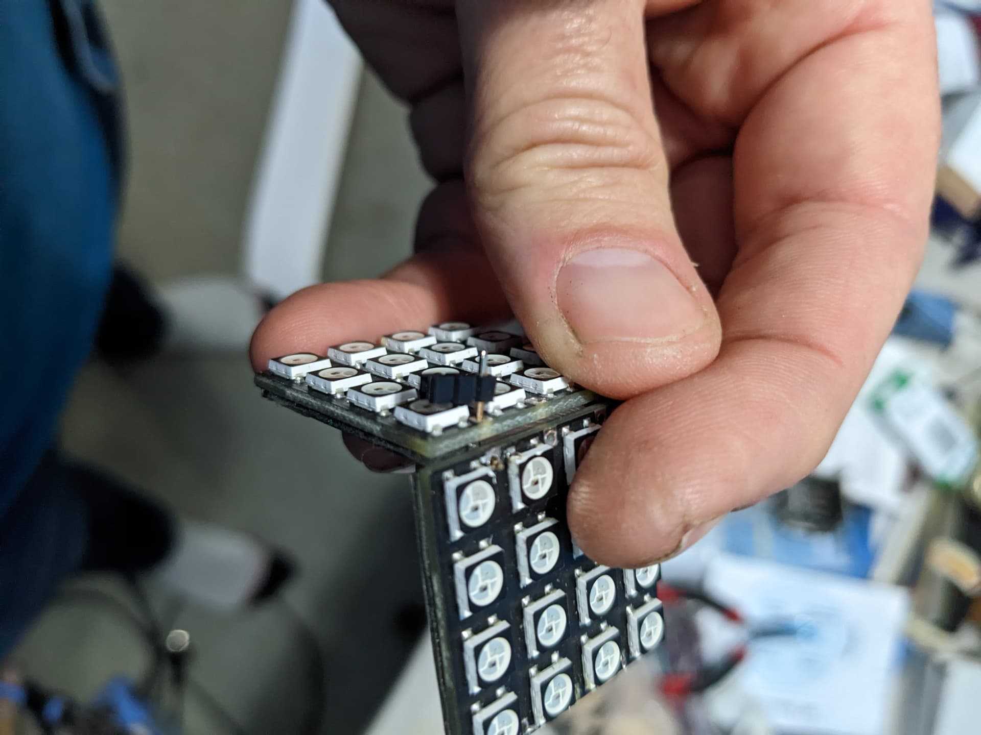
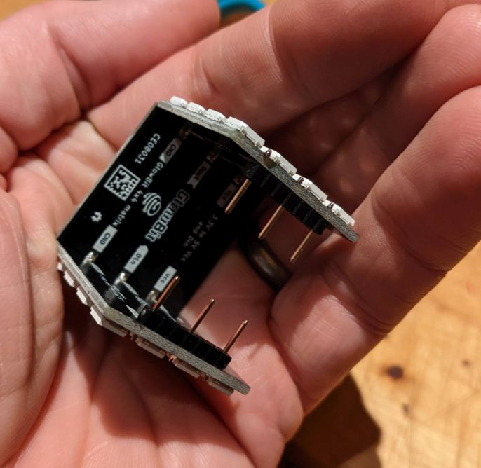
The new matricies arrived yesterday along with the right angle connectors. I took sections of 7 pins, removed 4 as shown, and soldered them on (see the 2 back panels)
I pulled off the plastic of the right angle connectors and soldered on the other panels. Then cut the pins short. I also added some straight pins to the outer sections. There are 2 of these.
It’s just friction fit and the headers at the ends of the U act as a stop. I’m going to add something to make it a little more secure, eighter magnets or lego
I had everything working with the XIAO RP2040 wit headers attached, but couldn’t fit it together. so I removed the headers and soldered wires to the holes. It fits together nicely, but the XIAO won’t connect and I get “device descriptor request failed” in device manager. The reset and boot select do nothing, the lights come on, but that’s it. I’ve removed the wires, tried again and double checked none of the pins are shorted… still the same.
I recon I killed it with my removing of the headers and/or soldering the wires
Anyway… I could just order another, but I’ve also got a PGA2040 I could use. With the PGA2040 I’ll need to solder everything in, including boot-sel and a usb connection (I’ve got a USB-C breakout I was planning on using with the PGA2040), though it’s got the advantage that I can leave the USB connector outside the glow bit box.
In either case I’ll need to connect things up. What’s the best/safest way to do that?
Headers and then attatch the headers?
Solder the wires directly into the through-holes?
if so, is any particular wire better?
Something else?
I’m also open to trying something to fix my existing XAIO RP2040
I’d say best practice is to have a connector, like header pins instead of directly soldering to your microcontroller. While direct soldering wires will save you precious space it will be very hard to diagnose or troubleshoot without sufficient wire slack and if you give your wires lots of slack then that’s too much wire-spaghetti to fit into the cube.
You could also try small pigtail leads as a half-way measure.
I wasn’t able to find any comprehensive reasons as to why this may be happening, to confirm your suspicions I’d say that something on the Xiao has let out the magic smoke.
To further Trent’s response about headers something with a low profile would also benifit, check out these listings:
With the PGA you might be able to pop the headers in and only connect the USB breakout when you have to program the module, then detach it once programmed!
Regardless of how you connect everything I’d try to insulate parts that shouldn’t short, electrical/Kapton tape
PS: Here’s a forum post @Liam120347, a community member made a little while back where he hacked up a Pico to make it a smidge smaller (at around 35mm I’m not certain that it would fit inside the cube but might be worth a shot!)
Yep. Also, it’s pretty cheep, only about 3 coffees (in Perth overpriced coffees)
Those look great! Thanks, I had no idea they existed.
BTW if I use the PGA2040, would I need to use pull up resistors for I2C? Or is that on the RP2040 chip. Everything I’ve seen says you don’t need it with the PI Pico, but it wasn’t clear if it was pico specific, or RP2040
Good analogy to price up parts for your project ahaha
With some sensors pull-ups are usually included there, some other supporting circuitry (check out the PiicoDev Expansion board with an inline 120-ohm resistor, another nice touch from the Engineering team )